Kısa Cevap
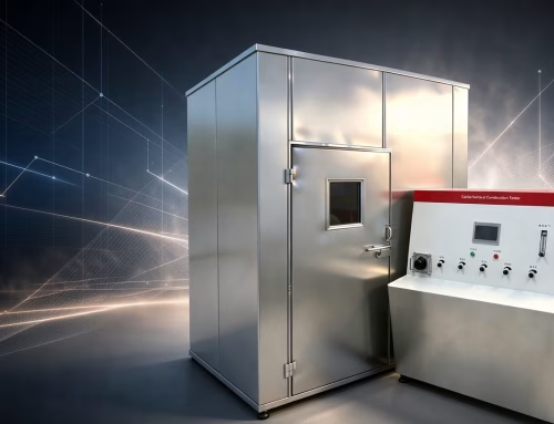
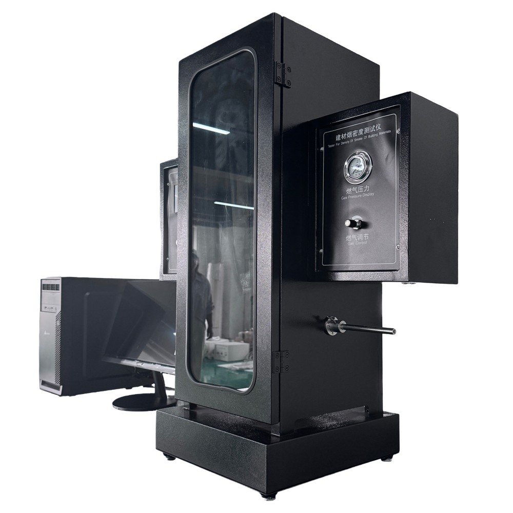
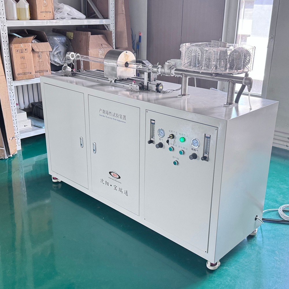
A smoke density tester measures how much a burning material’s smoke dims a light beam — optical density, not gas composition and not heat release. The core is a closed chamber holding a flat specimen, a calibrated radiant heater, and a vertical photometer whose light path crosses the smoke. The current international method is ISO 5659:2026 — renumbered from the withdrawn ISO 5659-2:2017 in January 2026 — with flat specimens ≤25 mm thick exposed at 25 veya 50 kW/m² 1 2. In the US, ASTM E662 defines the classic NBS smoke density chamber with vertical specimen mounting 3. The output is a set of Ds values — specific optical density over time — that specifications convert into pass/fail smoke limits.
What the Instrument Actually Measures
Smoke obscures light by scattering and absorption; the tester quantifies it as the attenuation of a calibrated light beam across a known path length inside the chamber. The raw signal is % light transmittance, converted into specific optical density (Ds) — a normalized value per unit chamber volume and beam path, so results are comparable between chambers of the same design. A typical run records transmittance continuously and reports the density curve plus key read-outs: the maximum Ds reached and Ds at fixed times.
What the number is not: it is not toxicity (gas species and concentrations need an FTIR gas-analysis chain — see smoke toxicity testing for building materials), and it is not the s1–s3 smoke class of EN 13501-1, which comes from the SBI test’s optical measurement 4. Three instruments, three different smoke questions — the most common specification error is treating them as interchangeable.
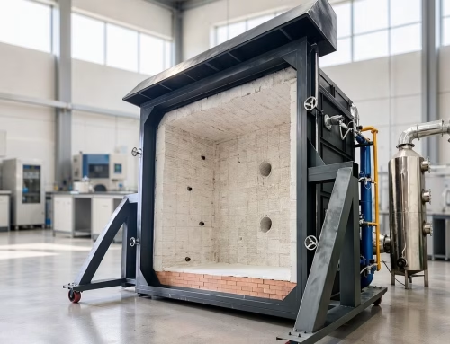
Inside the Chamber
| Bileşen | İşlev | What to check when buying |
|---|---|---|
| Radiant heater | Exposes the specimen at the set flux (25/50 kW/m² in ISO 5659) [1] | Flux calibration method and heat-flux meter inclusion |
| Specimen holders | Hold flat specimens ≤25 mm thick [1] | Holder set for both ISO 5659 and ASTM E662 geometries [3] |
| Pilot burner | Optional ignition source (flaming vs non-flaming modes) [1] | Presence and positioning per method |
| Photometer | Vertical light beam and detector across the smoke layer | Calibration filters and linearity documentation |
| Chamber body | Sealed, volume-defined enclosure | Seals, door interlocks, thermometry |
| Data system | Transmittance curve → Ds conversion | Exportable curves, not just summary numbers |
The photometer is the heart: its stability and calibration define data quality, which is why laboratories keep neutral-density filters for verification and document the light-path geometry in every report.
The chamber body itself matters more than it looks. Ds is normalized against a defined chamber volume, so the enclosure must actually hold that volume: worn door seals, a leaking purge connection or a lid that does not seat flat all change the effective volume and bias every number the chamber produces. Sealed does not mean static either — the smoke must reach the photometer beam in a reproducible way, which is why door interlocks, a defined closing sequence and internal thermometry appear in both method families’ apparatus descriptions [1][3]. When a specification asks for a smoke density result, it is implicitly asking for all of this hardware discipline; a chamber that cannot document seal condition and temperature stability is producing numbers nobody can defend in an audit.
The Two Test Modes
Every smoke density run is a choice between two exposures, and they tell different stories:
- Non-flaming (smouldering) mode — radiant heat only, no pilot flame. This is the pyrolysis question: how much smoke does the material make as it decomposes without igniting? Smouldering smoke is often denser and cooler.
- Flaming mode — radiant heat plus pilot flame. This is the burning question: how much smoke does sustained combustion produce?
Specifications normally fix both or one; a report that does not name the mode is incomplete. The mode matters commercially because the two results can rank materials differently — a product that smokes heavily in pyrolysis may burn clean, and vice versa.
In practice the mode is written into the test plan before the chamber is switched on, together with the flux and the specimen thickness, because the three choices interact. Development laboratories routinely run both modes on every formulation so the ranking question — which material is safer — gets answered on both pathways; acceptance laboratories run exactly the mode their specification names and nothing else, since a non-flaming result does not substitute for a flaming one in any audit we have seen. The pilot burner’s position and the moment it is applied are method-defined details, and they belong to the chamber’s control system, not to the operator’s judgement — another reason the apparatus rather than the technician is the audited object.
The Two Chamber Families: ISO 5659 vs ASTM E662
| Aspect | ISO 5659:2026 chamber [1] | ASTM E662 NBS chamber [3] |
|---|---|---|
| Specimen mounting | Horizontal, ≤25 mm thick | Vertical |
| Exposure | Radiant heater 25/50 kW/m², ±pilot | Radiant heater 2.5 W/cm², ±pilot |
| Standard origin | International (ISO), basis for rail EN 45545 smoke specs 5 | US practice, widely cited by transport and building specs |
| Headline output | Ds curve, max Ds, Ds at fixed times | Specific optical density Ds, Dm |
| Correlation | None established between the two methods [3] | — |
That last row is the clause laboratories quote most often: ASTM E662’s own scope states that correlation with other test methods has not been established, so an ISO 5659 result and an E662 result describe different exposures and are not interchangeable numbers [3]. The edition statuses are worth a line in any report check: ISO 5659:2026 güncel [1], ISO 5659-2:2017 is withdrawn [2], and the E662 document is cited without a year where the store page shows none (待确认 for the year when ordering).
The orientation difference is not cosmetic. A horizontal specimen lets molten material pool on the exposed face, which changes how the heater sees the surface and how smoke leaves the exposure zone; a vertical specimen lets melt run off and changes the ignition behaviour in the flaming mode. Neither arrangement is “better” — they simply answer the specification that names them. Procurement therefore follows the customer base: laboratories serving international rail and construction specifications buy into the ISO 5659 geometry [1][5], laboratories serving US transport and building programmes buy the E662 geometry [3], and the growing middle ground — suppliers who ship into both markets — is exactly who buys a dual-geometry chamber and keeps the two results on separate report lines.
A Worked Example: Reading a Ds Curve
Consider the shape of a run rather than any real product’s data. The chamber records transmittance T as a percentage that starts near 100 and falls as smoke accumulates; Ds rises in step, because specific optical density scales with the logarithm of the reciprocal transmittance. The table below is purely illustrative — it shows how the same relationship maps light loss onto the number a specification reads:
| Transmittance T | log₁₀(100/T) — Ds scales with this | What the operator sees |
|---|---|---|
| 90% | 0.05 | Clear; early exposure, smoke just reaching the beam |
| 75% | 0.12 | Slight haze visible in the chamber window |
| 50% | 0.30 | Dense smoke; the specification’s first danger zone |
| 25% | 0.60 | Very heavy obscuration; read-outs past this point are terminal |
| 10% | 1.00 | Near-total light loss; the curve has effectively plateaued |
Three reading habits follow from that shape. Birinci, a curve that drops early and steeply describes fast-obscuring material — more dangerous for evacuation than one that reaches the same maximum Ds late. Saniye, a plateau does not mean the material stopped decomposing, only that the obscuration rate balanced the chamber’s losses; the report still needs the time axis to say what happened when. Üçüncü, the number a specification demands — maximum Ds, or Ds at a fixed minute — must be read from the curve at the defined point, which is exactly why curve-level export appears on every buying checklist in this article. A chamber that prints only “pass” or a single maximum has thrown away the curve the whole argument rests on.
Reading the Numbers on a Report
A usable smoke density report carries: the standard and edition [1][2], the exposure mode (flux, pilot or not), specimen thickness, the transmittance curve, the Ds read-outs the specification demands, and the chamber’s calibration evidence. Where railway specifications apply, they read Ds at fixed times (commonly 1.5 Ve 4 dakika) against limits set by hazard level under the EN 45545-2 framework — the 2020 edition of that document was withdrawn in October 2023 with no successor yet listed, so confirm the applicable edition with the assessment body (待确认) [5]. Exact limit values belong to the specification, not to this article; the tester’s job is to produce the curve those limits are read against.
The findings that cost laboratories their audits repeat across files: a report with no exposure mode, an edition of the standard that was already withdrawn on the test date, a summary number that cannot be traced back to a stored curve, or calibration records that end before the test series began. None of these mean the physics went wrong — they mean the evidence chain did. The cheapest insurance is a chamber whose data system archives the raw transmittance trace with the metadata attached, because every one of those findings is answered by re-opening the file rather than re-running the test.
Calibration and Verification in Daily Use
A smoke density tester drifts in two places: the light path and the heater. Neither drift announces itself — the numbers still come out, they are just quietly wrong. That is why the verification schedule is a specification item, not a housekeeping detail.
| Kontrol etmek | What it verifies | Evidence the auditor asks for |
|---|---|---|
| Photometer zero and span | Beam, detector and electronics at 0% Ve 100% transmittance | Verification record dated before the test series |
| Neutral-density filter check | Linearity across the transmittance range, not just the endpoints | Filter serial numbers and measured vs nominal values |
| Heat-flux meter verification | Radiant heater delivering 25 / 50 kW/m² as claimed [1] | Meter calibration certificate and placement record |
| Chamber integrity | Seals, door seating, effective volume for Ds normalization | Seal inspection log; leak or seating check |
| Data-system audit trail | Curve stored with mode, flux, thickness metadata | Exported file inspection, not just the printed summary |
Two habits separate defensible laboratories from fragile ones. The first is checking the light path with a neutral-density filter at mid-range — a photometer can be perfect at 0% Ve 100% and wrong at 40%, right where the specification’s read-outs live. The second is verifying the heater flux with a calibrated meter at the specimen position, because the flux setpoint on the controller is a claim until the meter confirms it [1]. Both records belong in the same file as the test reports they support; a verification that cannot be produced on request did not, for audit purposes, happen.
Specifying a Smoke Density Tester
| Requirement | Neden önemli? |
|---|---|
| Both ISO 5659 and E662 holder sets | One chamber serving both method families avoids a second purchase [1][3] |
| Documented photometer calibration | Data quality lives in the light path |
| Flux verification kit | 25/50 kW/m² claims need a calibrated meter [1] |
| Mode switching (±pilot) | The two modes are separate specification questions [1] |
| Curve-level data export | Summary-only systems cannot be re-read for other specs |
BRT Testing builds the chamber for exactly this range — the building materials smoke density tester product page lists the configuration, and the same laboratory usually pairs it with the smoke toxicity test equipment chain when specifications also demand gas data.
Two final questions belong in any purchase conversation but rarely make the checklist. Throughput: a chamber that needs a long cool-down and a manual wipe-out between runs quietly caps how many specimens a laboratory can process in a specification cycle, and the constraint only shows up after delivery. Consumables and spares: heater elements, pilot tubing, seals and verification filters wear on a schedule, and a manufacturer who quotes lead times for those parts at order time is the one who keeps your chamber running through audit season. Ask both before signing; neither is visible on a datasheet.
Sıkça Sorulan Sorular
What is a smoke density tester?
A smoke density tester is a laboratory instrument that measures how strongly a burning or pyrolysing material’s smoke attenuates a light beam. It consists of a sealed chamber, a calibrated radiant heater, a specimen holder and a photometer; the result is a specific optical density curve over time. The two dominant methods are ISO 5659:2026 with horizontal specimens at 25 veya 50 kW/m² and ASTM E662 with vertically mounted specimens in the NBS-style chamber.
What does the Ds value mean?
Ds is the specific optical density — light attenuation normalised by the chamber volume and the light path length, so numbers compare across chambers of the same design. Reports typically quote the maximum Ds reached and Ds at fixed read times. Higher Ds means denser, more light-obscuring smoke; it says nothing about which gases the smoke contains.
Is smoke density the same as smoke toxicity?
HAYIR. Density measures light obscuration by smoke particles; toxicity measures the chemical species and concentrations in the fire effluent, usually by FTIR gas analysis. A material can produce thick smoke with harmless composition or thin smoke with dangerous gas concentrations. Specifications that care about evacuation visibility test density; those that care about incapacitation test toxicity — the equipment differs.
Why did ISO 5659-2 become ISO 5659?
ISO renumbered the document when the 2026 edition was published on 27 Ocak 2026: the withdrawn ISO 5659-2:2017 was replaced by ISO 5659:2026 with the same scope of measuring smoke production from exposed surfaces of materials and composites. Reports and QA files citing 5659-2 should be mapped to the new designation; the method itself — flat specimens, 25/50 kW/m², ±pilot — carried over.
Can one chamber run both ISO 5659 and ASTM E662?
Only if it carries both specimen-holder sets and the control range both methods require, because the two methods differ in specimen orientation, flux and procedure. The results still must not be mixed: ASTM E662’s scope states that correlation with other test methods has not been established, so a Ds from one method is not an estimate of the other. Laboratories serving both ISO-based and US-facing specifications buy a chamber configurable for both and report each against its own standard.
What should I look for when buying a smoke density tester?
Four things: documented photometer calibration with verification filters, a heat-flux verification kit for the 25 Ve 50 kW/m² exposures, specimen-holder sets covering the methods your specifications cite, and curve-level data export so a single test can be re-read against different requirements. A chamber that only prints summary numbers locks you out of future specifications.
Do smoke density results feed the Euroclass?
Not directly. The s1–s3 smoke classes of EN 13501-1 come from the SBI test’s optical measurements during the classification test, not from a standalone smoke density chamber run. The chamber feeds product-level and sector specifications — rail interiors, transport and project requirements — and supports development screening. A Euroclass claim and a Ds claim are separate documents from separate tests.
Çözüm: A Decision Order
- Name the smoke question: obscuration, or composition, or the SBI-derived class [1][4].
- Pick the method family the market cites: ISO 5659:2026 or ASTM E662 [1][3].
- Fix the exposure mode — flux and pilot — in the test plan [1].
- Buy the chamber once, with both holder sets and documented photometer calibration.
Start at the building materials smoke density tester product page or contact BRT Testing with your specification list.
About the Author
Metrobüs Testi (Shenyang Baoruitong Automation Equipment) manufactures smoke density chambers, smoke toxicity and gas-analysis equipment and reaction-to-fire benches for construction-product and transport-interior laboratories. The content team writes from the instrument side — chamber control, photometer calibration and the reporting that keeps Ds data defensible. Edition facts above were verified against UNI and ASTM catalogue entries in November 2026.
Kaynaklar
- UYKU — BÜYÜK 5659:2026, Fire tests — Measurement of smoke production from exposed surfaces of materials and composites, güncel baskı (27 Jan 2026); flat specimens ≤25 mm exposed at 25 veya 50 kW/m². https://webstore.uni.com/en/iso-5659-2026
- UYKU — BÜYÜK 5659-2:2017, withdrawn and replaced on 2026-01-27 by ISO 5659:2026 (renumbering record). https://webstore.uni.com/en/iso-5659-2-2017
- ASTM International — E662, Standard Test Method for Specific Optical Density of Smoke Generated by Solid Materials; scope covers vertical specimen mounting and states that correlation with other test methods has not been established. https://store.astm.org/e662.html
- UNI—EN 13501-1:2018, Fire classification of construction products and building elements — Part 1: Classification using data from reaction to fire tests, güncel baskı (19 Dec 2018). https://webstore.uni.com/en/en-13501-1-2018
- UNI—EN 45545-2:2020, Railway applications — Fire protection of rolling stock — Part 2: Requirements for fire protection of passenger cars; withdrawn 11 Oct 2023, no successor listed in the UNI catalogue. https://webstore.uni.com/en/en-45545-2-2020