- What the Standard Requires of an ISO 5660 Kegelkalorimeter
- How an ISO 5660 Cone Calorimeter Produces a Heat Release Curve
- Reading an ISO 5660 Cone Calorimeter Datasheet Against the Clauses
- Choosing the Irradiance Level
- Calibrating an ISO 5660 Kegelkalorimeter: The Evidence an Assessor Asks For
- Where ISO 5660-1 Sits Among National Frameworks
- Configuring an ISO 5660 Cone Calorimeter for a Real Test Menu
- Procurement and Commissioning Errors That Show Up in the Data
- Häufig gestellte Fragen
- What is an ISO 5660 cone calorimeter used for?
- How does oxygen consumption calorimetry produce a heat release rate?
- What specimen size does ISO 5660-1 require?
- Why is the oxygen analyser’s transport delay limited to 60 Sekunden?
- Which irradiance level should a laboratory choose?
- Are ISO 5660-1 und ISO 5660-2 both current?
- What is MARHE and why does it matter for railway products?
- Abschluss: A Decision Order for Specification
Four subsystems decide whether your ISO 5660 cone calorimeter produces data that survives interlaboratory comparison: the cone heater’s irradiance uniformity, the load cell’s drift and response time, the oxygen analyser’s transport delay and noise, and the radiation shield’s insertion timing. Sample size, touchscreen layout and report templates are visible on a quotation; those four are usually not, yet they are the ones ISO 5660-1 pins down with numbers.
Everything below is written against the third edition of ISO 5660-1 (2015, corrected 2021), the edition that cancelled and merged the old Part 1 and Part 2 into one method document 1. If your laboratory is preparing an ISO/IEC 17025 scope extension, the clauses cited here are the ones an assessor will open the standard to.
What the Standard Requires of an ISO 5660 Kegelkalorimeter
The standard assesses the heat release rate and the dynamic smoke production rate of specimens exposed in the horizontal orientation to controlled irradiance with an external igniter [1]. Heat release comes from oxygen consumption calorimetry; smoke comes from laser attenuation; time to ignition — strictly, the onset of sustained flaming — is recorded in the same run [1].
That framing matters because ISO 5660-1 is a method specification, not a product specification. It never says “the calorimeter shall be accurate to X percent.” Instead it prescribes the apparatus in uncomfortable detail and prescribes the calibrations that keep that apparatus honest. The instrument is the calibration evidence.
The Measurement Principle, Stripped Down
The method rests on the observation that the net heat of combustion is generally proportional to the oxygen consumed, at approximately 13.1 × 10³ kJ of heat per kilogram of oxygen [1]. The specimen burns in ambient air under a preset external irradiance anywhere between 0 Und 75 kW/m², while the instrument tracks oxygen concentration and exhaust gas flow rate [1]. Nothing about the fuel’s chemistry needs to be known in advance; the oxygen balance carries the answer.
Smoke follows a different law. Light transmitted through combustion products decays exponentially with distance — Bouguer’s law — so the fraction of laser intensity that survives the exhaust duct yields an extinction coefficient, which multiplied by volumetric flow gives the smoke production rate [1]. Obscuration is logged for the whole test whether or not the specimen flames, which is how non-flaming pyrolysis is captured at all [1].
What the 2015 Edition Changed
The third edition cancels and replaces both ISO 5660-1:2002 und ISO 5660-2:2002, and the two documents were technically revised and merged [1]4. The practical consequence for anyone writing a test scope is simple: ISO 5660-2 no longer exists as a separate part. A datasheet that lists “ISO 5660-1/2” as two live standards is describing a 2002-era structure. The family now runs Part 1 (the method), Part 3 (a Technical Specification giving guidance on measurement) and Part 4 (heat release for determination of low levels of combustibility), which remains under preparation [1].
A corrected version published in January 2021 incorporated a single correction, to Formula (4) [1], and Amendment 1 followed in 2019, so the citable reference is the 2015 edition as amended and corrected; the catalogue record and the current project stage are both public 23. Anyone still working from an uncorrected 2015 PDF is calculating with a superseded expression.
How an ISO 5660 Cone Calorimeter Produces a Heat Release Curve
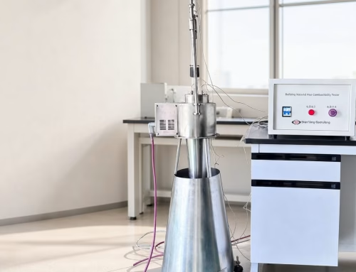
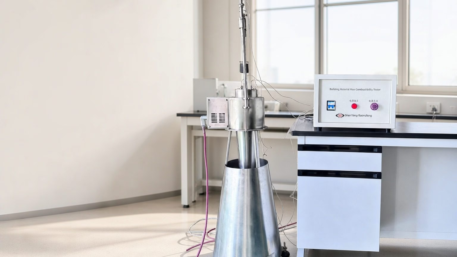
The ISO 5660 Cone Calorimeter Hardware Chain
The instrument is a chain, und ISO 5660-1 specifies every link, because a heat release rate is only as credible as the weakest one. The heater is a 5 000 W electrical rod wound tightly into a truncated cone and encased in a double-wall stainless steel shell filled with refractory fibre blanket of nominal 13 mm thickness and 100 kg/m³ density [1]. Irradiance is held by controlling the average temperature of three thermocouples in contact with the element, and uniformity inside the central 50 mm × 50 mm of the exposed face must stay within ±2 % bei 50 kW/m², with the control loop holding that average to ±10 °C [1].
Below it sits the radiation shield — total thickness not exceeding 12 mm, either water-cooled and matt black at emissivity 0.95 ± 0.05 or non-water-cooled with a reflective or ceramic top — which protects the specimen before t = 0 Und, in practice, defines when the test starts [1]. The specimen holder is a square pan with a (106 ± 1) mm opening and (25 ± 1) mm depth in 2.4 ± 0.15 mm stainless steel, lined with at least 13 mm of 65 kg/m³ ceramic fibre blanket; the retainer frame’s (94.0 ± 0.5) mm square opening defines the exposed area that per-unit values are normalised to [1].
One geometry rule causes more re-testing than any other. Heater-to-specimen separation is (25 ± 1) mm, Und (60 ± 1) mm for materials that intumesce or deform; the standard states plainly that ignition times measured at 60 mm are not comparable with 25 mm results [1].
| Mounting geometry | Required value | Why it is checked |
| Heater base to specimen surface | (25 ± 1) mm | Sets the irradiance actually received by the surface |
| Heater base to specimen, intumescing materials | (60 ± 1) mm | Mandatory once a specimen can touch the igniter or the heater; ignition times are not comparable with 25 mm results [1] |
| Specimen holder opening | (106 ± 1) mm, (25 ± 1) mm deep | Determines whether the specimen fits without edge gaps |
| Retainer frame face opening | (94.0 ± 0.5) mm square | Defines the exposed area used for kW/m² normalisation |
| Holder base lining | ≥13 mm at 65 kg/m³ | Backing insulation changes measured heat release |
The Four Subsystems That Decide Data Quality
The weighing device must resolve 0.1 G, hold an accuracy of ±0.3 g or better, carry at least 500 G, respond from 10 % Zu 90 % within 4 S, und nicht mehr treiben als 1 g over 30 Minuten [1]. Read those five figures together, because a quotation that advertises only 0.1 g resolution names the least interesting one: a load cell that resolves 0.1 g but drifts several grams per half hour cannot produce a defensible mass loss rate.
The oxygen analyser must be of the paramagnetic type, span at least 0 % Zu 25 % oxygen, hold drift and noise within 50 µl/l over 30 Minuten, and reach 10 % Zu 90 % of full scale in under 12 S [1]. Its transport delay through the sampling line must be determined and must not exceed 60 S [1]. Because analysers are pressure-sensitive, an absolute pressure transducer and an isothermal enclosure within 2 °C of a preset value between 30 °C und 70 °C are also required [1].
Three quieter components matter just as much — the spark igniter, the methane calibration burner and the Schmidt-Boelter working heat flux meter — and each is specified numerically in the acceptance table below [1]. The data system must sample at least every second and store a minimum of 720 points per parameter [1].
Reading an ISO 5660 Cone Calorimeter Datasheet Against the Clauses
Most specification sheets quote capabilities; ISO 5660-1 quotes limits. The table below puts them side by side so you can mark up a quotation without the standard open.
| Specification | What ISO 5660-1 requires | Why the gap matters in a quotation |
| Cone heater power and flux | 5 000 W; irradiance up to 75 kW/m² | A 100 kW/m² ceiling is useful headroom for R&D, but only the 0–75 kW/m² band is inside the method |
| Irradiance uniformity | Within ±2 % over the central 50 mm × 50 mm at 50 kW/m² | Quoted as “±2 %” elsewhere? It is a positional figure, not a power-supply figure |
| Heater temperature control | Average of three thermocouples held within ±10 °C | PID accuracy alone does not prove this; the three-thermocouple averaging must be shown |
| Radiation shield | Non-combustible, ≤12 mm total thickness, automated insertion | Shield lag shifts the effective start of the test and corrupts time-to-ignition |
| Weighing device | 0.1 g resolution, ±0.3 g accuracy, ≥500 g capacity, ≤4 s response, ≤1 g drift per 30 min | The thermal barrier around the load cell, not the resolution, determines the drift figure |
| Oxygen analyser | Paramagnetic, ≥0–25 %, ≤50 µl/l drift and noise per 30 min, <12 s response | NDIR oxygen cells appear in quotations without equivalence evidence; the clause names paramagnetic |
| Oxygen transport delay | Determined per method and ≤60 s | Long sampling lines plus soot filters are the usual cause of a failure here |
| Gas sampling ring | 12 holes of (2.2 ± 0.1) mm, (685 ± 15) mm from the hood, facing away from flow | Hole orientation prevents soot clogging — a detail vendors rarely quote |
| Exhaust flow measurement | Orifice plate (57 ± 3) mm internal diameter, ≥350 mm of straight duct on both sides | Undersized straight runs make the flow coefficient unstable over time |
| Heat flux meter | Schmidt-Boelter thermopile, (100 ± 10) kW/m², water-cooled, ±0.5 % repeatability | Often sold separately; without it the heater cannot be calibrated at all |
| Data acquisition | 1 Hz minimum, ≥720 points per parameter, oxygen channel to 50 µl/l | Long-duration intumescent tests need far more than 720 points in practice |
Two numbers in that table are worth memorising because they come up in every audit: ±2 % irradiance uniformity over the central 50 mm × 50 mm, Und ≤60 s oxygen transport delay. Both are measurable in the lab, and both are the first things a peer reviewer asks about when two laboratories disagree.
Choosing the Irradiance Level
ISO 5660-1 permits any preset irradiance from 0 Zu 75 kW/m², so the test level comes from the product standard or the research question, not from the instrument [1]. IN 45545-2 for railway materials requires the cone heater to impose two different irradiance levels — 25 kW/m² and 50 kW/m² — with the applicable one depending on where the product sits in the vehicle 11.
For most building-product and polymer programmes, 50 kW/m² represents a developed fire and 25 kW/m² an early-stage exposure, while some furniture and cable protocols specify 35 kW/m². Whatever level is chosen must be documented, because heat release rate is strongly irradiance-dependent.
| Irradiance | Typical role | Which documents drive it |
| 25 kW/m² | Early-stage exposure; lower-radiation product locations | IN 45545-2 requirement sets at 25 kW/m²; several cable and furniture protocols |
| 35 kW/m² | Intermediate / custom research comparison | Internal R&D matrices rather than a single published requirement |
| 50 kW/m² | Developed-fire exposure; the default in most building-product programmes | IN 45545-2 requirement sets at 50 kW/m²; ASTM E1354 practice 5 |
| Up to 75 kW/m² | Upper end of the range permitted by the method | ISO 5660-1 irradiance range [1] |
Calibrating an ISO 5660 Kegelkalorimeter: The Evidence an Assessor Asks For
ISO 5660-1 does not only describe hardware; it describes the calibration programme that keeps that hardware inside its specification. Preliminary calibrations cover the irradiance control response, weighing response time and drift, oxygen analyser delay, response, noise and drift, and the effect of optional side screens [1]. Operating calibrations then cover weighing accuracy, the oxygen analyser check, heat release calibration with the methane burner, heater calibration against the working heat flux meter, and smoke meter calibration with neutral density filters of optical density 0.3 Und 0.8 bei 632.8 nm [1].
The heat flux meter carries its own traceability requirement: it is checked against two reference instruments of the same type held as standards, one of which is fully recalibrated at a standardising laboratory every year [1]. Less frequent calibrations cover the linearity of heat release rate measurement and the accuracy of the calibration burner flow meter [1].
| Verification item | Reference or artefact | Akzeptanzkriterium | Clause |
| Irradiance control response | Cone heater thermocouples | Average held within ±10 °C of preset | 6.4 / 10.1.2 |
| Weighing device drift | Load cell, no specimen | ≤1 g over 30 min | 6.5 / 10.1.4 |
| Weighing device response | Step load | 10 %–90 % in ≤4 s | 6.5 / 10.1.3 |
| Weighing device accuracy | Calibrated masses | ±0.3 g or better | 6.5 / 10.2.2 |
| Oxygen analyser delay | Step change in sampled gas | Transport delay td ≤60 s | 6.9 / 10.1.5 |
| Oxygen analyser noise and drift | Zero and span gases | ≤50 µl/l over 30 min | 6.12 / 10.1.6 |
| Heater calibration | Working heat flux meter | Preset irradiance reproduced within the control band; uniformity ±2 % bei 50 kW/m² | 6.2 / 10.2.5 |
| Heat release rate calibration | Methane calibration burner, ≥99.5 % purity | Flow meter accurate to ±3 % of the reading at 5 kW | 6.14 / 10.2.4 |
| Smoke meter calibration | Neutral density filters OD 0.3 Und 0.8 | k = 2.303 D′ / L reproduced | 6.19 / 10.3 |
| Working heat flux meter | Two reference meters, same type | One reference recalibrated annually at a standardising laboratory | 6.13 / Anhang F |
Because a laboratory’s competence claim rests on ISO/IEC 17025, this calibration programme is not paperwork — it is the OQ and PQ evidence for the instrument. Practically, the artefacts that must be ordered with the calorimeter are the calibration burner, the working heat flux meter with its reference pair, the neutral density filter set, and certified span gases. A quotation for an ISO 5660 cone calorimeter that omits them is not a lower price; it is an incomplete instrument.
Where ISO 5660-1 Sits Among National Frameworks
Heat release rate is the central measurement in reaction-to-fire testing because it quantifies fire size, the rate of fire growth and, indirectly, the release of smoke and toxic gases 10. The cone method has been adopted across national and regional systems, which is why one instrument can serve several compliance routes at once.
| Framework | Document | What the cone calorimeter covers |
| International | ISO 5660-1:2015 (corrected 2021) | The method specified in this guide; the third edition merged the former Part 2 on smoke production rate [1][2] |
| North America | ASTM E1354 | Standard test method for heat and visible smoke release rates using a cone calorimeter [5] |
| North America | NFPA 271 | Determination of degrees of combustibility using an oxygen consumption calorimeter 6 |
| China | GB/T 16172-2026 | Building material heat release and smoke production rate; wirksam 2026-08-01 and a modified adoption of ISO 5660-1:2015 8 |
| China, superseded | GB/T 16172-2007 | Previous edition, withdrawn on 2026-08-01 and equivalent to the 2002 ISO text 9 |
| Railway | IN 45545-2 | Heat release expressed as MARHE at 25 or 50 kW/m², applied across requirement sets and hazard levels [10][11] |
Beyond compliance work, the instrument is a research tool: NIST has published cone calorimeter evaluations of composite flammability in which per-unit-area heat release data feed models that predict full-scale fire development 7. That dual role is why calorimeter time is often shared between certification, screening and academic work, provided calibration is documented for each use.
The instrument most often confused with it is the Single Burning Item apparatus under EN 13823. SBI uses an L-shaped specimen of roughly 1.5 m by 1.0 m and drives the Euroclass classification in EN 13501-1, while the ISO 5660 cone calorimeter works at bench scale [1]. The two share the oxygen consumption calorimetry principle but answer different regulatory questions, and we keep a separate comparison of the SBI apparatus and the cone calorimeter for laboratories choosing between them.
Configuring an ISO 5660 Cone Calorimeter for a Real Test Menu
A single ISO 5660 cone calorimeter model covers this whole measurement family, so selection is about configuration rather than tiers. The ZXLR Cone Calorimeter from BRT is built to ISO 5660-1 and ASTM E1354 with a 5 000 W radiant cone heater and an automated radiation shield, and the table below maps its published specifications onto the clauses above.
| Subsystem | ZXLR published specification | Clause it addresses |
| Radiant cone heater | 5 000 W, 0–100 kW/m², centre uniformity ≤±2 %, PID + SSR control at ±10 °C | 6.2 cone heater, 6.4 irradiance control [1] |
| Radiation shield | 6 mm non-water-cooled stainless steel, program-driven insertion and retraction | 6.3 radiation shield, ≤12 mm thickness [1] |
| Weighing system | 0–1 000 g range, 0.1 g resolution, <4 s response, ≤1 g drift per 30 min, dual thermal barrier | 6.5 weighing device, all four criteria [1] |
| Probenmontage | 100 mm × 100 mm specimen, thickness up to 50 mm, 25 mm separation | 6.6 holder and 6.7 retainer frame geometry [1] |
| Gas analysis | Sampling pump, soot filters, drying column, paramagnetic / NDIR O₂ plus CO and CO₂ channels | 6.9 sampling apparatus, 6.12 oxygen analyser [1] |
| Exhaust and smoke | Soot filters, cold traps, laser smoke obscuration measurement in the duct | 6.8 exhaust system, 6.17 smoke measuring system [1] |
| Data system | Dual touchscreen plus PC software, automatic real-time HRR / THR / MLR / EHC / SPR curves, one-click PDF export | 6.15 data collection and analysis system [1] |
The optional CO and CO₂ channels deserve a deliberate decision rather than an up-sell. ISO 5660-1 permits carbon monoxide and carbon dioxide measurement as an addition and applies different heat release formulae when they are used, set out in Annex G [1]. Railway and cable programmes usually want them; building-product screening rarely does.
Procurement and Commissioning Errors That Show Up in the Data
The mistakes that cost accredited laboratories the most time are rarely about the heater. They are about the interfaces around it.
| Error | What it looks like six months later | Prevention |
| Auditing resolution and ignoring drift | Mass loss rate curves that wander upward during a 20-minute test | Require a 30-minute drift log at handover, per clause 6.5 [1] |
| Accepting an NDIR oxygen cell without equivalence data | Oxygen channel noise above 50 µl/l, or unexplained HRR baseline offsets | Ask for the analyser type in writing against clause 6.12 [1] |
| Long, unheated sampling lines | Transport delay above 60 S, and a heat release curve that lags the mass loss curve | Measure and record td during commissioning, per clause 6.9 [1] |
| Heat flux meter bought later | Heater cannot be verified, so the whole OQ package stalls | Order the meter and its two reference instruments with the calorimeter, per Annex F [1] |
| No neutral density filters | Smoke calibration improvised with materials instead of artefacts | Specify the OD 0.3 Und 0.8 filter set at 632.8 nm, per clause 6.19 [1] |
| Undersized exhaust duct runs | Orifice calibration that drifts whenever the ductwork is disturbed | Confirm ≥350 mm straight sections each side of the orifice plate, per clause 6.8 [1] |
| Assuming 100 mm specimens on every product | Retainer-frame results compared with unframed results | Fix a written mounting protocol; the exposed face differs between the two |
Häufig gestellte Fragen
What is an ISO 5660 cone calorimeter used for?
It measures the heat release rate and dynamic smoke production rate of a small horizontal specimen exposed to controlled radiant heat with an external igniter [1]. Accredited laboratories use it for material screening, development support, production control and rail or building-product certification. Because the output is per unit area, it feeds fire growth models rather than replacing full-scale tests.
How does oxygen consumption calorimetry produce a heat release rate?
The method assumes the net heat of combustion is proportional to the oxygen consumed, at roughly 13.1 × 10³ kJ per kilogram of oxygen [1]. The instrument measures oxygen concentration and exhaust gas flow rate in the combustion product stream, and the deficit between inlet and outlet oxygen converts into heat release. No knowledge of the specimen’s chemistry is needed, which is why composites work.
What specimen size does ISO 5660-1 require?
Specimens are essentially flat and cut to roughly 100 mm square; the holder opening is (106 ± 1) mm and the retainer frame, when fitted, defines a (94.0 ± 0.5) mm square exposed face [1]. Thickness is limited by holder depth and by the (25 ± 1) mm separation between heater base plate and specimen surface. Intumescing materials run at (60 ± 1) mm, and their ignition times are not comparable [1].
Why is the oxygen analyser’s transport delay limited to 60 Sekunden?
The analyser samples gas through a probe, filters and drying train, so its reading corresponds to combustion that happened earlier in the duct. That lag, td, must be determined by the method and must not exceed 60 S [1]. A longer delay shifts the heat release curve relative to the mass loss curve, making time to peak heat release rate unreliable in short tests.
Which irradiance level should a laboratory choose?
ISO 5660-1 allows any preset irradiance between 0 Und 75 kW/m², so the level is set by the product standard or the research question [1]. IN 45545-2 for railway materials requires two levels, 25 Und 50 kW/m², and which applies depends on the product’s location in the vehicle [11]. Results at different levels are never directly comparable.
Are ISO 5660-1 und ISO 5660-2 both current?
NEIN. Der 2015 third edition of ISO 5660-1 cancelled and replaced both ISO 5660-1:2002 und ISO 5660-2:2002, and the two were technically revised and merged [1]. Smoke production rate measurement now sits inside Part 1 as a dynamic measurement. The family is Part 1, Part 3 on measurement guidance, and Part 4, still under preparation [1].
What is MARHE and why does it matter for railway products?
MARHE is the Maximum Average Rate of Heat Emission: an average rate of heat emission is calculated from the heat release rate curve, and the maximum of that running average is reported [10]. IN 45545-2 adopted MARHE because it is far less sensitive to measurement noise than a single peak value, and it predicts full-scale fire development robustly [10]. Thresholds depend on requirement set and hazard level, and the mean of three specimens is typically reported [11].
Abschluss: A Decision Order for Specification
If you are specifying an ISO 5660 cone calorimeter for accredited work, work through the decision in this order rather than from the quotation’s feature list:
- Confirm the method edition. ISO 5660-1:2015 with the 2021 correction is current, ISO 5660-2 is no longer a separate part, und GB/T 16172-2026 has replaced the 2007 Ausgabe [1][8].
- Fix the test menu before the configuration. Irradiance levels, product families, CO/CO₂ channels and whether intumescing materials will run at 60 mm separation all change the specification.
- Demand the four subsystems as numbers. Irradiance uniformity (±2 % over 50 mm × 50 mm), load cell drift and response, oxygen analyser type and delay, and automated shield timing [1].
- Buy the calibration artefacts with the instrument. Methane burner, working heat flux meter plus two reference meters, the OD 0.3 Und 0.8 filter set, and certified span gases.
- Require the OQ/PQ dataset at handover. Drift logs, response times, the oxygen delay measurement and the first heat release calibration should arrive as records, not assurances.
- Settle the software workflow early. Curve export, raw data retention and report generation are what an assessor reads months later [1].
If your test menu spans both bench-scale heat release and intermediate-scale classification, that choice shapes your capital plan more than any specification line — see our SBI versus cone calorimeter comparison and the wider building material fire testing standards guide.
Send us your test menu and intended scope, and the BRT engineering team will map it against the ZXLR Kegelkalorimeter configuration, including the calibration artefacts and the acceptance record you will need at your next ISO 17025 assessment. Browse the full Brand- und Flammenprüfgeräte range or the measurable test parameters for context.
Über den Autor: prepared by the BRT Testing fire-testing engineering team in Shenyang, China, and checked against the official ISO 5660-1:2015 preview text and the published EN 45545-2 heat release requirements.