- What IEC 60331 Actually Measures
- The Parts of the IEC 60331 Series, and Which Ones Still Apply
- Reading the 830 °C Fire and Shock Condition
- What the Specimen Setup Requires
- How a Test Run Proceeds
- Where IEC 60331 Sits Among Cable Fire Tests
- Buying an IEC 60331 Test System: What to Specify
- Common Misreadings of IEC 60331
- Frequently Asked Questions
- What is the IEC 60331 cable fire resistance test?
- What is the difference between IEC 60331-1, -2 and -3?
- Is IEC 60331-21 still valid?
- What is the difference between IEC 60331 and IEC 60332?
- What temperature and duration does the test use?
- How does the cable pass or fail?
- Does IEC 60331 include water spray or mechanical shock?
- What should I check in a supplier’s IEC 60331 test report?
- Conclusion: How to Specify IEC 60331 Correctly
IEC 60331 is the international series that asks one question — does a cable keep working while it is burning? The current parts, IEC 60331-1, -2 and -3, expose an energised cable to a flame of at least 830 °C plus repeated mechanical shock, and the cable passes only if it maintains continuity for the full duration. The older parts -11, -21, -23 and -25 tested the same idea at a flame temperature of at least 750 °C with fire alone, and IEC lists them as withdrawn. If you are buying cable or apparatus today, build your specification around the 830 °C fire-with-shock parts and treat any 750 °C claim as legacy evidence.
What IEC 60331 Actually Measures
The standard defines its own central term. Clause 3.1 of IEC 60331-1 calls circuit integrity the “ability of an electric cable to continue to operate in a designated manner whilst subjected to a specified flame source for a specified period of time under specified conditions” [1]. Every design choice in the test flows from that sentence: the cable is not merely observed, it is expected to keep functioning.
This is where most procurement confusion starts. A flame-retardant cable tested under IEC 60332 limits how far fire spreads along a tray, but the cable is not required to stay electrically alive. A fire-resistant cable tested under IEC 60331 is energised throughout the exposure and must not trip, short or drop below its specified performance. A cable can hold a flame-spread rating while failing circuit integrity in minutes.
Because the cable carries voltage during the test, the measurement is electrical rather than visual. A fuse in the continuity circuit, specified by reference to IEC 60269-3, acts as the pass/fail detector: if the fuse opens, the cable has lost integrity and the test stops [1]. Temperatures are read with thermocouples conforming to IEC 60584-1, so the flame condition itself is traceable [1].
The Parts of the IEC 60331 Series, and Which Ones Still Apply
The series has been extended and reshaped since its first edition in 1970, and the current structure separates the 830 °C fire-with-shock methods from an older family of fire-only procedures [2]. A certificate quoting a withdrawn part is therefore describing a different test, not a different number for the same test.
| Part | Scope | Flame condition | Status |
| IEC 60331-1:2018 | Cables ≤ 0.6/1.0 kV with overall diameter exceeding 20 mm | ≥ 830 °C fire with mechanical shock | Current |
| IEC 60331-2:2018 | Cables ≤ 0.6/1.0 kV with overall diameter not exceeding 20 mm | ≥ 830 °C fire with mechanical shock | Current |
| IEC 60331-3:2018 | Cables ≤ 0.6/1.0 kV tested inside a metal enclosure | ≥ 830 °C fire with mechanical shock | Current |
| IEC 60331-4:2024 | Power cables rated above 1 kV up to 30 kV | ≥ 830 °C fire with mechanical shock | Current |
| IEC 60331-11 / -21 / -23 / -25 | Apparatus and procedures for power, data and optical fibre cables | ≥ 750 °C fire alone | Withdrawn (no longer maintained) |
Notice how the dividing line works. Parts 1, 2 and 3 split by cable geometry rather than by application: diameter above 20 mm, diameter at or below 20 mm, and a sample mounted inside a metal enclosure such as conduit or trunking. IEC 60331-3 adds one qualification worth reading twice — a cable assessed by that method should first have been assessed against Part 1 or Part 2, and the earlier result is normally visible through the optional marking described in Clause 11 [3].
Reading the 830 °C Fire and Shock Condition
The headline figure in Part 1 is a flame temperature of at least 830 °C applied together with mechanical shock, and the standard recommends flame application times of 30, 60, 90 or 120 minutes depending on the performance being claimed. All three current low-voltage parts include shock — there is no current sub-part that tests fire resistance in the IEC 60331 family with fire alone.
The shock device matters more than buyers usually expect. It simulates structural material falling onto an energised cable, so the impacts are delivered at fixed intervals during the flame period rather than as a single blow. Part 4 gives the same logic to medium-voltage cables, restricting the method to conductor sizes up to and including 120 mm², with results for that size qualifying larger cross-sections of the same construction [4].
Two details from Part 4 are useful when you are writing a specification. Annex A supplies the verification method for the burner and control system, and Annex C offers optional guidance for water spray or water jet protocols [4]. A supplier who can produce an Annex A verification record is describing a controlled heat source, not a burner that happens to reach temperature.
Why mass flow control became mandatory
The second edition of Parts 1 and 2 made mass flow meters or controllers the required means of setting fuel and air input to the burner [5]. The reasoning is repeatability: a pressure-only gas train drifts with supply conditions, while a mass flow controller holds a set flow, so the flame produced in your verification run matches the flame in the test run. If you are comparing apparatus, ask which control method is fitted.
The test environment is part of the result
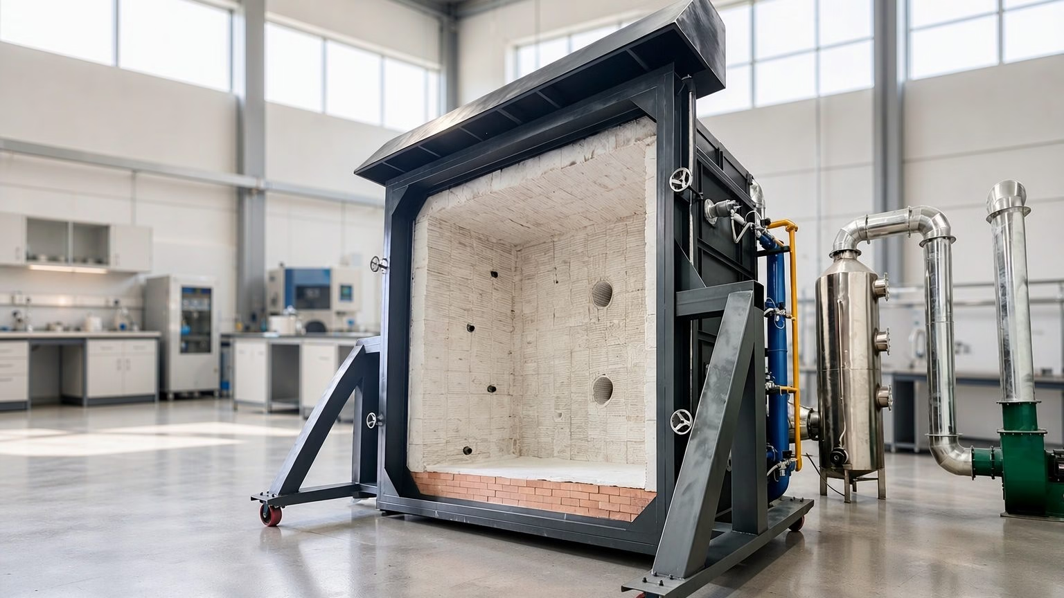
Part 1 requires a draught-free environment inside a chamber of at least 20 m³ with provision for exhausting noxious gases, and the air inlets and chimney must be positioned so the flame stays stable during both verification and test [1]. Chamber volume is therefore not a marketing number. A flame that wanders changes the heat flux reaching the specimen, and the result stops being comparable with another laboratory’s.
What the Specimen Setup Requires
Before the flame is lit, the sample has to be prepared and mounted in a way the standard can defend. Preparation removes the outer covering at the ends far enough to make clean electrical connections, and mounting follows a defined geometry on a steel test ladder.
The 2018 revision changed that ladder deliberately. It now carries two extra vertical elements so it can accommodate single-core cables without a concentric metal layer, and cables whose bending radius in normal use is larger than approximately 400 mm [5]. A laboratory still using the older layout is testing a geometry the current standard does not describe for those constructions. Mounting method also differs between single-core cables with a concentric metal layer and multicore cables, and between those and single cores without such a layer.
Continuity checking is wired in parallel with the specimen. The arrangement for cables rated up to and including 600 V / 1 000 V is defined in the standard, and although the scope stops at 0.6/1.0 kV, the procedure may be extended to cables rated up to and including 1.8/3 (3.3) kV by agreement between manufacturer and purchaser provided suitable fuses are used [1].
How a Test Run Proceeds
A run follows a fixed sequence, and each step is checkable in the report.
- Verify the heat source. The burner and its control system are verified before the cable is tested, using the procedure in Annex A.
- Prepare and mount the specimen. The cable is stripped at the ends, fitted to the test ladder at the specified bending geometry, and positioned relative to the burner.
- Energise the circuit. Rated voltage is applied and the continuity arrangement, including the fuse, is confirmed as closed.
- Apply flame and shock. The burner is lit and the shock device delivers impacts at the defined intervals for the selected flame application time.
- Judge on continuity. The cable passes if the circuit survives the full exposure without the fuse opening; a break at any point ends the test.
Steps one and three are the ones most often undocumented in supplier literature. A test report that shows the flame curve, the fuse rating, the mounting figure and the pass criterion is a report you can audit.
What separates a usable report from a claim
The pass criterion is continuity under a defined flame with a defined fuse. A report that omits the flame curve, the fuse rating or the mounting geometry cannot be checked against the clause it claims to satisfy, and a buyer has no way to tell a 120-minute result from a 30-minute one.
Where IEC 60331 Sits Among Cable Fire Tests
IEC 60331 answers a different question from the other cable fire standards, and reading them as a ladder of severity leads to wrong specifications. The table below sets out the adjacent tests by what they evidence.
| Standard | Question it answers | Cable state during test |
| IEC 60331 | Does the circuit keep working in fire? | Energised, under flame and shock |
| IEC 60332 | Does fire spread along the cable? | Not required to stay operational |
| IEC 61034 | How much smoke is released? | Smoke density measurement |
| IEC 60754 | What gases are released? | Halogen acid gas and acidity measurement |
| EN 50200 | Small unprotected cables plus water spray | Fire with shock and water |
| BS 6387 | British protocols C, W and Z | Fire alone, with water, with shock |
The useful mental model is that IEC 60331 is the only one of these that treats the cable as a live circuit. A hospital, metro tunnel or data centre specification normally needs several: 60332 for spread, 61034 and 60754 for smoke and gases on escape routes, and 60331 for the circuits that must keep running.
Buying an IEC 60331 Test System: What to Specify
Apparatus for this family has to satisfy the environment, the heat source and the electrical load at the same time, and the specification sheet should be read in that order. The comparison below summarises what a compliant chamber needs, next to what varies between suppliers.
| Requirement | What the standard implies | What to check on a quotation |
| Test environment | Draught-free chamber, minimum 20 m³, fume exhaust | Chamber volume and draught-shield provision |
| Heat source control | Mass flow meters/controllers mandatory | Pressure-only train vs mass flow control |
| Flame condition | ≥ 830 °C for Parts 1–3; ≥ 750 °C for withdrawn parts | Achievable range and verification method |
| Burner verification | Annex A procedure with recorded result | Whether Annex A records are supplied |
| Specimen mounting | Steel test ladder with the 2018 vertical elements | Ladder drawing and bending-radius provision |
| Continuity circuit | Fuse per IEC 60269-3, defined for ≤ 600 V / 1 000 V | Fuse ratings and short-circuit detection |
| Shock application | Repeated impacts at defined intervals | Interval control and impact energy record |
| Optional water protocols | Annex C guidance in Part 4 | Water spray or jet capability, if required |
| Reporting | Point of failure, continuity data, test report content | Logged flame curve and time of failure |
Two entries in that table carry most of the procurement risk. Mass flow control is mandatory under the current editions, so a rig without it cannot claim to perform the 2018 method as written. Annex A verification is the other: it is the evidence that the flame you tested with is the flame the standard describes.
Where the BRT chamber fits
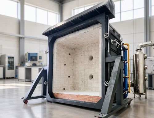
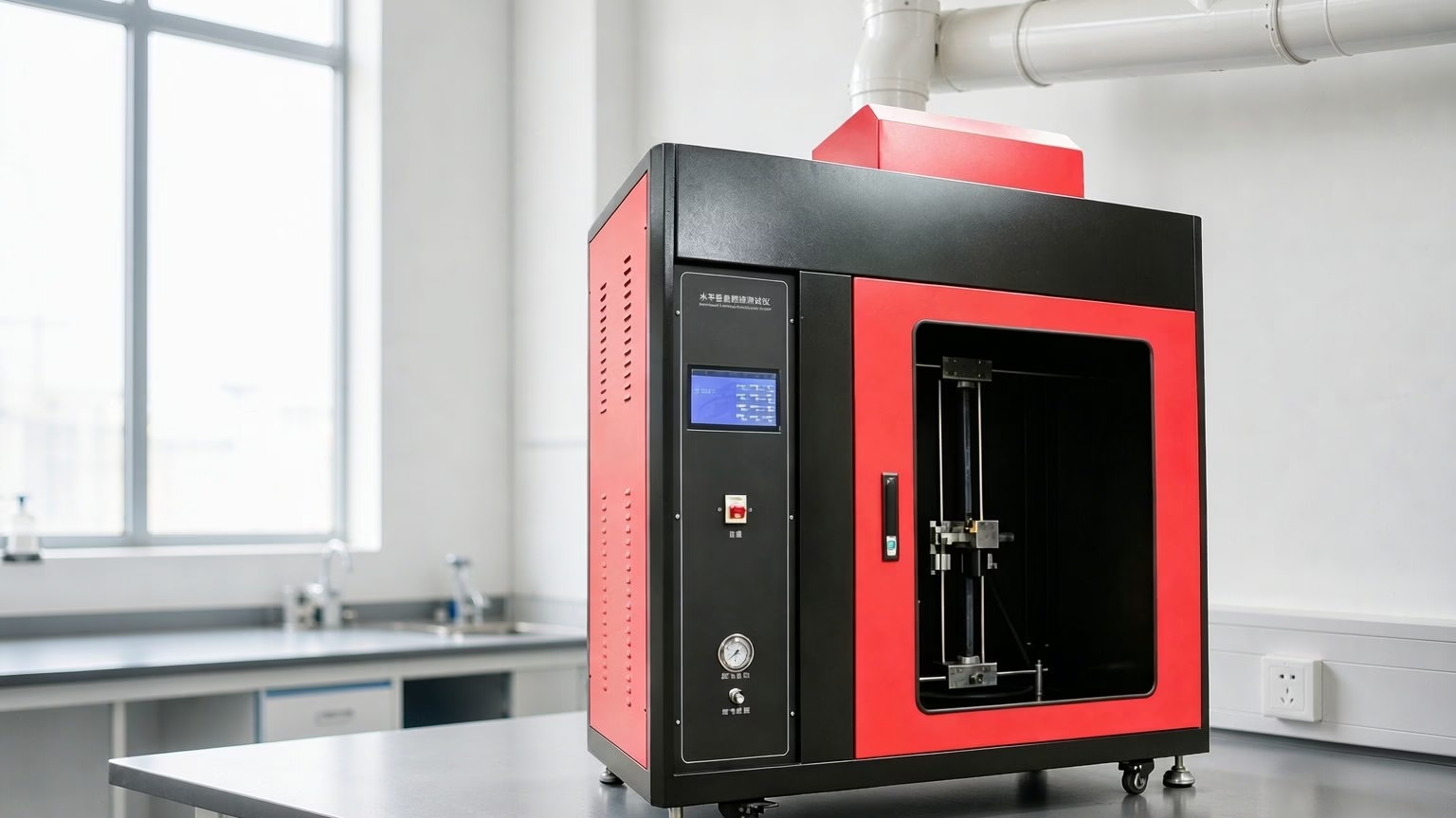
You can compare the apparatus on our fire and flame testing equipment page, or start from the test parameter you need to prove on the select by test parameter page. The BRT NH-016 cable fire resistance tester is built around this family, with a 3.0 m × 3.0 m × 3.0 m 304 stainless steel chamber, mass flow gas control and a five-circuit adjustable load for simultaneous specimens.
Common Misreadings of IEC 60331
Treating 750 °C as current. Parts 21, 23 and 25 were written around fire alone at a flame temperature of at least 750 °C, and IEC has withdrawn them with the note that Parts 1 and 2 are the recommended test procedures [2]. A datasheet quoting “90 min at 750 °C” is citing the legacy series accurately, but not the current method.
Assuming shock is optional. All three current low-voltage parts include mechanical shock. A quotation for an “IEC 60331 chamber” that offers no shock device is not configured for the current method.
Reading 90 minutes as the required duration. The standard recommends 30, 60, 90 or 120 minutes depending on the performance claimed, so the duration in a certificate should match your project specification rather than the other way round.
Confusing fire resistance with flame retardancy. IEC 60332 limits spread; IEC 60331 keeps the circuit alive. Choosing the wrong one for an emergency circuit is a life-safety error, not a paperwork one.
Accepting a one-line certificate. The pass criterion is continuity under a defined flame with a defined fuse. Without the flame curve, the fuse rating and the mounting figure, “passed” cannot be verified.
Frequently Asked Questions
What is the IEC 60331 cable fire resistance test?
It is a family of tests that check whether an energised cable keeps working while exposed to fire. The current parts, IEC 60331-1, -2 and -3, apply a flame of at least 830 °C together with repeated mechanical shock, and the cable passes only if it maintains circuit continuity for the full flame application time — typically 30, 60, 90 or 120 minutes — without the continuity fuse opening.
What is the difference between IEC 60331-1, -2 and -3?
The parts divide by cable geometry rather than by application. IEC 60331-1 covers cables with an overall diameter exceeding 20 mm, IEC 60331-2 covers cables not exceeding 20 mm, and IEC 60331-3 covers cables tested inside a metal enclosure such as conduit or trunking. All three use the same 830 °C fire-with-shock condition and the same continuity logic.
Is IEC 60331-21 still valid?
IEC 60331-21, along with Parts 11, 23 and 25, has been withdrawn and is no longer subject to maintenance, while IEC notes that Parts 1 and 2 are the recommended test procedures. Certificates citing these parts describe a real test — fire alone at a flame temperature of at least 750 °C — but they do not evidence the 830 °C fire-with-shock method now in force.
What is the difference between IEC 60331 and IEC 60332?
IEC 60332 measures whether fire spreads along a cable; the cable is not required to keep operating. IEC 60331 measures whether the cable keeps working during fire, with voltage applied and continuity monitored throughout. A cable can pass flame-spread testing and still lose circuit integrity within minutes, so emergency circuits are specified against 60331 rather than 60332.
What temperature and duration does the test use?
The current parts specify a flame of at least 830 °C with mechanical shock, and the standard recommends flame application times of 30, 60, 90 or 120 minutes. The legacy fire-only parts used a flame temperature of at least 750 °C. Duration should follow the performance your project requires, not the highest figure available.
How does the cable pass or fail?
The cable is energised at rated voltage and a fuse is placed in the continuity circuit. The cable passes if the circuit survives the entire flame and shock period with the fuse intact. If insulation breaks down, conductors short, or the fuse opens, the test ends at that moment and the time to failure is recorded.
Does IEC 60331 include water spray or mechanical shock?
Mechanical shock is included in all three current low-voltage parts, so a compliant apparatus needs a shock device. Water spray is not part of the core 830 °C method; optional water spray or water jet protocols are given as guidance in Annex C of IEC 60331-4, and water-based requirements otherwise come from standards such as EN 50200 or BS 6387 Protocol W.
What should I check in a supplier’s IEC 60331 test report?
Look for the part number and edition, the flame temperature curve from the verified burner, the fuse rating used in the continuity circuit, the mounting arrangement including bending geometry, the flame application time, and the recorded time of failure or confirmation of continuity. A report without the flame curve and fuse rating does not let you verify that the current method was performed.
Conclusion: How to Specify IEC 60331 Correctly
Work through the decision in this order.
- Identify the cable and the geometry. Diameter above or below 20 mm, and whether the installation runs inside metal enclosure, decide whether Part 1, -2 or -3 applies.
- Confirm the flame condition you need. Use the 830 °C fire-with-shock parts for new specifications; treat 750 °C fire-only claims as legacy evidence.
- Fix the duration from the project requirement. Choose 30, 60, 90 or 120 minutes from the performance the circuit must deliver, not from the highest available number.
- Require the verification and continuity records. Mass flow control and an Annex A verification record, with the fuse rating and mounting geometry stated in the report.
- Pair 60331 with the smoke and spread tests. Add 60332, 61034 and 60754 so the specification covers spread, smoke and corrosive gases alongside circuit integrity.
If you are configuring a circuit integrity chamber or need to match a test scope to an existing certificate, get in touch with the cable construction and the standard parts you must evidence, and our engineering team will confirm the burner, shock and load configuration that fits.
This article was prepared by the engineering content team at Shenyang Baoruitong Automation Equipment Co., Ltd. (BRT Testing), a manufacturer of fire and flame test apparatus with more than 15 years of experience and ISO 9001/13485 certification. Technical statements are referenced to the IEC 60331 series and verified against the official standard previews and IEC catalogue records listed below.