- What the ISO 1133 Melt Flow Index Test Covers, and What It Deliberately Leaves Out
- How a Melt Flow Index Test Works
- Procedure A vs Procedure B: Choosing Before You Start
- The Melt Flow Index Test Procedure, Step by Step
- Reading the Result: From Cut-Off Mass to a Reportable Number
- Decoding the ISO 1133 Test Conditions Table
- How Repeatable Is a Melt Flow Index Test Result?
- Where ISO 1133 and ASTM D1238 Diverge
- Choosing an MFI Tester for ISO 1133 Work
- Frequently Asked Questions
- What is the ISO 1133 melt flow index test?
- Is MFI the same as MFR and MVR?
- What is the difference between Procedure A and Procedure B in ISO 1133?
- How do I choose an MFI tester for ISO 1133?
- What are the standard test conditions in ISO 1133?
- How repeatable is a melt flow index test result?
- When should ISO 1133-2 be used instead of ISO 1133-1?
- Do ISO 1133 and ASTM D1238 give the same result?
- Conclusion: A Decision Order for Melt Flow Rate Testing
An ISO 1133 melt flow index test rarely fails because the instrument was poor. It fails because the procedure was skipped. A valid MFR result stands on five acceptance rules that must hold at once: cut-offs are 10–20 mm long and no more than 240 s apart, at least three cut-offs are weighed individually to the nearest 1 mg, the spread between the heaviest and lightest stays within 15 % of their average, and the run finishes within 25 min of the end of charging. Break any one and the standard tells you to discard the result, not to report it with a caveat. Interpretation starts after that, and the first thing to know is that at a mean MFR of 43.4 g/10 min, ISO 1133-1’s own interlaboratory data puts the between-laboratory reproducibility limit at 20.8 % 12. Always quote the condition with the number.
What the ISO 1133 Melt Flow Index Test Covers, and What It Deliberately Leaves Out
ISO 1133-1:2022 is the current edition — the second, published in June 2022 as a minor revision of the 2011 text, changing only references to withdrawn standards plus editorial points. No test parameter moved [1][2]3. A page still citing “ISO 1133:2005” is two editions out of date.
The ISO 1133 melt flow index test yields two properties by two procedures: Procedure A is a mass-measurement method giving MFR in g/10 min; Procedure B is a displacement-measurement method giving MVR in cm³/10 min. Each converts to the other if the melt density at the test temperature is known [2].
Two scope boundaries matter commercially. The standard notes that MVR is particularly useful when comparing materials of different filler content, because the mass figure carries density differences the volume figure does not [2]. It also warns against over-reading its own output: shear rates here are far lower than in processing, so results “will not always correlate with their behaviour during processing. Both methods are used primarily in quality control.” [2]
How a Melt Flow Index Test Works
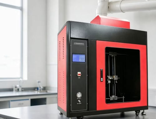
The apparatus for the ISO 1133 melt flow index test is an extrusion plastometer held at a fixed temperature. Resin sits in a vertical cylinder; a piston loaded with a known mass pushes the melt through a capillary die; the extrudate is either weighed over time or tracked by piston displacement. Every dimension in that chain is tolerance-controlled, and tighter than most buyers assume. These are the numbers to check against a supplier’s datasheet [2]:
| Component | ISO 1133-1:2022 requirement | Why it decides your result |
| Cylinder bore | (9.550 ± 0.007) mm, length 115–180 mm | Sets the pressure at the die. Wear is invisible but shifts the flow rate monotonically. |
| Die bore | Circular to within ± 0.005 mm of Ø 2.095 mm; length (8.000 ± 0.025) mm | The single most sensitive dimension. A chipped or worn die is a reject, not a rounding error. |
| Die material / finish | Tungsten carbide or hardened steel; Vickers hardness ≥ 500; Ra < 0.25 µm | Wall friction at the capillary changes apparent viscosity. |
| Piston head | Diameter (9.474 ± 0.007) mm; head length (6.35 ± 0.10) mm | Clearance against the bore controls leakage past the head. |
| Reference marks | Two annular marks (30 ± 0.2) mm apart on the stem | The timing window for both procedures is defined by these marks, not by the operator’s stopwatch start. |
| Cylinder temperature | Deviation at 10 mm above the die ≤ ± 1.0 °C; across 10–70 mm ≤ ± 2.0 °C (125 ≤ T < 250 °C) | Melt viscosity is temperature-driven. This is the error term that grows fastest with instrument age. |
The temperature band loosens as the test temperature rises: ± 2.5 °C across 10–70 mm for 250 ≤ T < 300 °C, and ± 3.0 °C at 300 °C and above, while the ± 1.0 °C figure at the die face holds throughout [2]. That asymmetry is deliberate — the die entrance is where the pressure drop happens.
Procedure A vs Procedure B: Choosing Before You Start
The choice is not a preference. ISO 1133-1 sets an accuracy requirement on the measurement channel, and it tightens as flow rate rises [2]:
| MFR / MVR range | Displacement accuracy | Time accuracy |
| 0.1 to 1.0 g/10 min or cm³/10 min | ± 0.02 mm | ± 0.1 s |
| > 1.0 to 100 | ± 0.1 mm | ± 0.1 s |
| > 100 | ± 0.1 mm | ± 0.01 s |
| Multiple measurements from a single charge, any flow rate | ± 0.1 mm | ± 0.01 s |
Two consequences follow. Automating a low-flow melt flow index test buys nothing on the displacement channel but everything on operator consistency; automating a high-flow test is effectively mandatory, because hand-timing a cut-off of a few seconds introduces more error than the instrument does. Note the last row: several readings from one charge impose the strictest time resolution regardless of flow rate.
Procedure A carries an escape clause: if the resin flows too slowly, or swells so much that no 10 mm cut-off is possible within 240 s, the method may still be used — but only if each cut-off weighs more than 0.04 g [2]4.
The Melt Flow Index Test Procedure, Step by Step
The ISO 1133 melt flow index test procedure runs on two routes. Procedure B is the shorter, and Procedure A is simply Procedure B with cut-offs added [2].
- Verify the cylinder temperature — do not trust the setpoint. Verification uses a calibrated sensor 10 mm above the die, and the apparatus must sit vertically; a piston leaning under load adds friction that reads as viscosity.
- Charge the cylinder. Sample mass follows the expected flow rate. Powders, flakes and film fragments usually need pre-compacting into a void-free charge, which is what Annex C covers. Trapped air is the commonest cause of repeatability failure, and it looks like scatter, not a defect.
- Preheat for 5 min, then load. The preheat runs from the completion of charging; if the piston was unloaded or underloaded during it, the load goes on at the end. Degradation-prone resins may need less, high-melting resins more. Bubbles in the extrudate mean the charge was not compacted.
- Measure. For MVR, record piston travel over a set time, or the time for a set distance. For MFR, cut at fixed intervals targeting 10–20 mm, and stop when the upper reference mark reaches the top of the cylinder.
- Weigh and judge. Discard any cut-off containing visible bubbles, weigh the rest individually to the nearest 1 mg, and take at least three.
The acceptance rules that decide validity
Then apply the acceptance rules — the step that separates a reportable result from a rejected one [2]:
| Acceptance rule | Threshold | What it protects against |
| Cut-off length | ≥ 10 mm, preferably 10–20 mm; maximum interval 240 s | Timing error dominating the mass measurement |
| Number of cut-offs | At least three, weighed individually | A single unrepresentative strand |
| Balance accuracy | Nearest 1 mg | Quantisation error on small cut-offs |
| Spread between cut-offs | Maximum minus minimum ≤ 15 % of the average, or discard and repeat on a fresh charge | Air voids, incomplete melting, thermal drift within the run |
| Weighing order | Record in order of extrusion; a continuous trend is “unusual behaviour” and must be reported | Progressive degradation or cross-linking mid-test |
| Total run time | End of charging to end of last measurement ≤ 25 min | Thermal degradation inflating the apparent flow rate |
| Low-flow fallback | If no 10 mm cut-off is achievable in 240 s, each cut-off must exceed 0.04 g or Procedure B applies | Unreportable small-sample scatter |
The 15 % rule is skipped most often and explains most “bad batches” that turn out to be bad tests. The 25 min ceiling matters too: a run that drifts long reads materially high, because mid-test chain scission lowers viscosity and the meter reads that as flow.
Reading the Result: From Cut-Off Mass to a Reportable Number
The arithmetic is trivial, which is why reporting errors are so common [2][4]8:
Three reporting rules travel with the number. Express the result to three significant figures, with a maximum of two decimal places. Record the temperature and load alongside it — MFR 10.6 g/10 min (190 °C/2.16 kg), not MFR 10.6. And mark the die: above 75 g/10 min a half-size die of 1.050 mm bore and 4.000 mm length is permitted, the result carries the subscript MFRh or MVRh, and no spacer may be fitted beneath it to restore the apparent 8.000 mm length [2].
Decoding the ISO 1133 Test Conditions Table
Why the condition letters disappeared
Most published guidance is out of date here. The familiar condition letters — A for 250 °C/2.16 kg, D for 190 °C/2.16 kg, M for 230 °C/2.16 kg and the rest — are no longer part of the standard. Annex A of ISO 1133-1:2022 is a temperature-by-load grid whose own footnote sends readers needing those letters back to ISO 1133:1997 [2]9.
That grid is normative table A.1: temperatures of 100, 125, 150, 190, 200, 220, 230, 235, 240, 250, 260, 265, 275, 280 and 300 °C crossed with nominal loads of 0.325, 1.20, 2.16, 3.80, 5.00, 10.00 and 21.60 kg. Any combination may be used [2].
Where the real conditions live
The conditions themselves live in the material standards, and Annex B says where: ISO 17855 (PE), ISO 19069 (PP), ISO 19062 (ABS), ISO 21305 (PC), ISO 29988 (POM), ISO 24026 (PMMA), ISO 24022 (PS), ISO 21301 (E/VAC), ISO 21302 (PB) [2]. A purchase specification that names only “MFR to ISO 1133” has not specified the test.
| Material | ISO condition commonly cited | Note |
| PE (LDPE, LLDPE, HDPE) | 190 °C / 2.16 kg | The original “melt index” condition; higher loads to 21.6 kg for high-viscosity pipe grades |
| PP homo- and copolymer | 230 °C / 2.16 kg | Datasheet default for most PP grades |
| ABS, SAN, ASA | 220 °C / 10.00 kg | High load to drive a high-viscosity melt |
| PC | 300 °C / 1.20 kg | Low load, high temperature — this is the condition where temperature control quality shows |
| PMMA | 230 °C / 3.80 kg | |
| POM | 190 °C / 2.16 kg | |
| PA 6 / PA 66 | 275 °C / 5.00 kg | Drying is mandatory; residual moisture raises apparent MFR |
| Non-rigid PVC | ASTM D3364 conditions | PVC has no ISO 1133 equivalent — the ASTM method is an extension of D1238 and uses shear rates near 1 s⁻¹ to detect plasticiser and stability effects |
The PVC row matters for supplier contracts: ASTM states there is no known ISO equivalent to D3364 7. Demanding “ISO 1133” for flexible PVC asks for a test that does not exist in that family.
How Repeatable Is a Melt Flow Index Test Result?
This is the question buyers ask least and should ask first.
What the interlaboratory data show
ISO 1133-1 publishes 2007 interlaboratory data on a high-flow polypropylene at 230 °C / 2.16 kg, with the caveat that a high-flow material’s precision is unlikely to represent the method at all flow rates [2][3]:
| Method | Labs | Mean value | Within-lab SD (Sr) | Repeatability limit (r) | Between-lab SD (SR) | Reproducibility limit (R) |
| MFR | 8 | 43.4 g/10 min | 2.2 % | 6.2 % | 7.4 % | 20.8 % |
| MVR | 16 | 59.3 cm³/10 min | 1.6 % | 4.5 % | 3.7 % | 10.5 % |
Read the last column. Two competent laboratories testing the same material can legitimately differ by 20.8 % on MFR and 10.5 % on MVR, while the repeatability limit — same lab, same operator, same instrument — is 6.2 % and 4.5 %.
That explains a great deal of commercial friction. A buyer writes a ± 5 % incoming-material tolerance on MFR — tighter than the method’s own repeatability limit — then rejects compliant deliveries because the certificates came from different labs.
Three practices that absorb the spread
- Specify a window, not a point. “MFR 0.9–1.1 g/10 min at 190 °C/2.16 kg” is usable. “MFR ≈ 1.0” is not.
- Compare MVR when density varies. The standard recommends it for filled compounds, and the round-robin supports it: MVR reproduced to 10.5 % against MFR’s 20.8 % on the same material, because the volume measurement carries no melt-density uncertainty [2].
- Match the tolerance to the limit. One laboratory running both reference and sample is governed by the repeatability limit; a cross-laboratory comparison by the reproducibility limit.
ASTM notes precision data have not been developed below 0.15 g/10 min or above 900 g/10 min 6; outside that band the number is an indicator, not a conformance value.
Where ISO 1133 and ASTM D1238 Diverge
The two standards share die geometry and are routinely quoted as if interchangeable. ASTM D1238 says so in a note to its own scope: the standards “address the same subject matter, but differ in technical content” [6].
| Parameter | ISO 1133-1 | ASTM D1238 |
| Current edition | ISO 1133-1:2022 (2nd ed., June 2022) | ASTM D1238-26, active, last updated 06 Aug 2026 5 |
| Procedures | A (mass) and B (displacement) | A (manual cut-off, ≈ 0.15–50 g/10 min), B (automated, ≈ 0.50–1500 g/10 min), C (half-die, polyolefins > 75 g/10 min), D (multi-load flow rate ratio) |
| Half-size die bore | 1.050 mm nominal | 1.048 ± 0.005 mm nominal [6] |
| Preheat after charge | 5 min | 7.0 ± 0.5 min [6] |
| Thermal stabilisation | Per the apparatus manufacturer’s procedure | Cylinder stabilised within ± 0.2 °C for at least 15 min before the test [6] |
| Moisture- and history-sensitive resins | Separate part, ISO 1133-2 | Handled within the single method |
| Flow rate ratio | Clause 10, single definition | Procedure D; results not directly comparable with Procedure A or B [6] |
The differences that change a result
The preheat difference is small in isolation and decisive at the margin: it sets how much of the charge has melted when the piston starts moving — exactly where a borderline grade sits. A certificate quoting one standard and a laboratory testing to the other are not the same measurement.
Choosing an MFI Tester for ISO 1133 Work
An MFI tester is bought once and used for a decade, so the headline temperature range is not the specification that matters. Three capabilities decide whether it satisfies ISO 1133-1:2022 or merely references it.
| Capability | Why it decides whether the instrument is usable |
| Die and barrel tolerance, plus a wear path | The die bore is the only dimension that degrades measurably in service. Without a documented go/no-go gauge procedure and a consumable die, results drift quietly. |
| A calibrated load set matched to your resins | Loads turn one instrument into a test method for several materials. A set spanning 0.325 kg to 21.600 kg covers the full ISO Annex A load list. |
| Temperature control you can verify, not just set | ISO 1133-1 requires the deviation to be measurable at 10 mm and 70 mm above the die. A ± 0.2 °C stability claim is not a demonstrated ± 1.0 °C at the die face under load. |
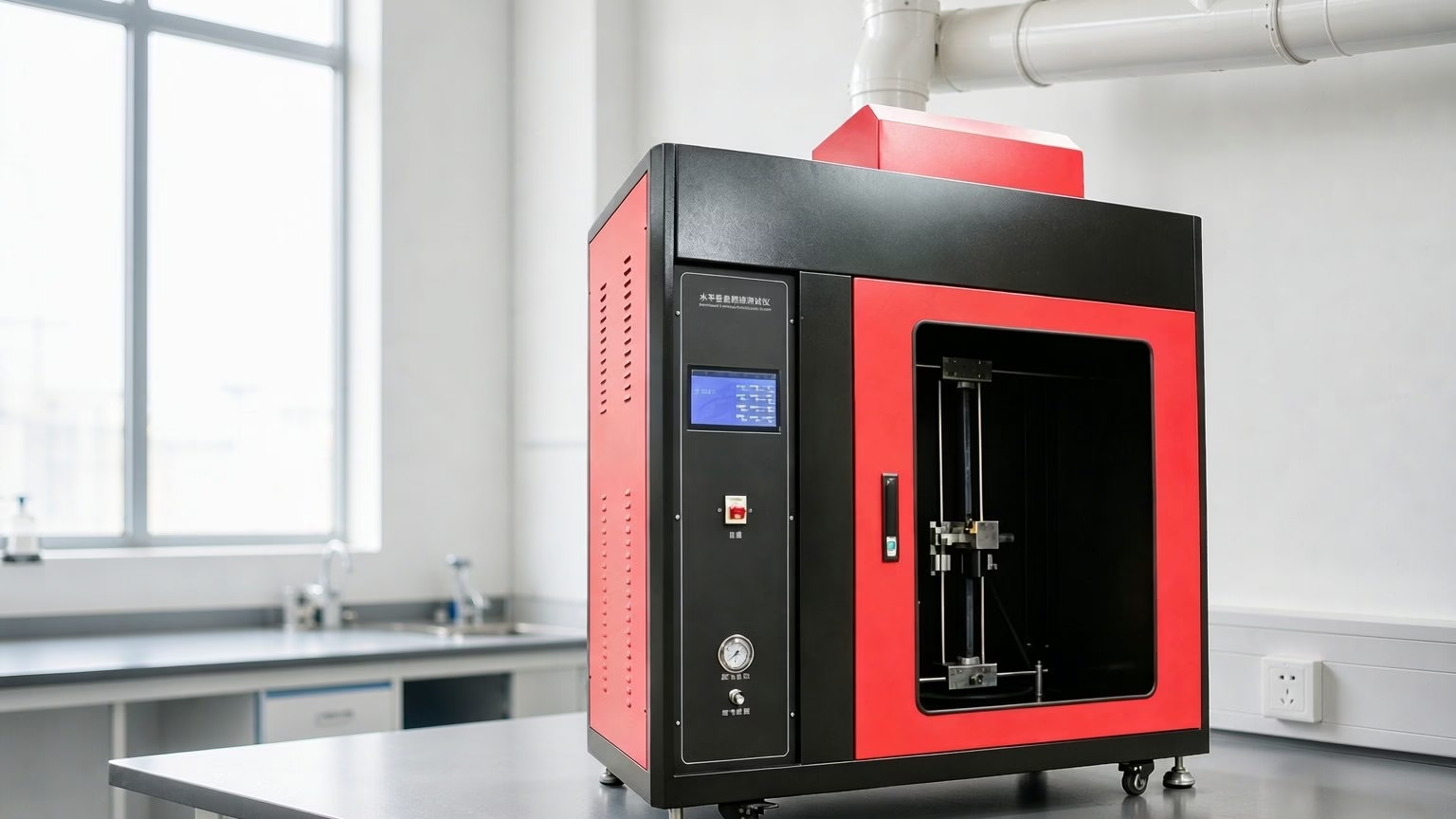
The BRT-400B is our extrusion plastometer for this work. Its published specification aligns to the current standard as follows:
| Parameter | BRT-400B specification | ISO 1133-1:2022 position |
| Die (orifice) | Ø 2.095 ± 0.005 mm × 8.000 ± 0.025 mm | Matches the standard die definition |
| Governed standards claimed | ISO 1133, GB/T 3682, ASTM D1238, ASTM D3364 | Correct scope; ASTM D3364 applies to non-rigid PVC only |
| Temperature range / control | 30 °C to 450 °C, ± 0.2 °C | Covers every test temperature in Annex A table A.1 |
| Standard load levels | 8 levels, 0.325 kg to 21.600 kg | Covers the entire ISO Annex A load list plus the 12.500 kg ASTM condition |
| Cylinder | Ø 9.550 mm, length 152 mm | Length inside the 115–180 mm range |
MFI tester details and quotation
What MFR cannot tell you
Three companion instruments cover what MFR cannot:
| What you need to know | Instrument | Why MFR alone cannot answer it |
| Melting and crystallisation behaviour | Differential scanning calorimeter | MFR is a single-point viscosity index; DSC resolves melting range and crystallinity |
| Softening under heat and load | Vicat softening temperature / HDT tester | Thermal performance limits, not flow |
| Carbon black and filler dispersion | Carbon black content tester | Filler content shifts MFR without any change in the polymer itself |
For PE pipe grades the ISO 1133 melt flow index is the incoming-material check and the hydrostatic pressure tester is the long-term performance test; our pipe testing standards guide maps where each sits.
Frequently Asked Questions
What is the ISO 1133 melt flow index test?
It measures how fast a molten thermoplastic extrudes through a defined capillary under a set temperature and load. ISO 1133-1:2022 defines two procedures: Procedure A weighs timed cut-offs and reports melt mass-flow rate (MFR) in g/10 min; Procedure B tracks piston displacement and reports melt volume-flow rate (MVR) in cm³/10 min. The conditions come from the material standard — 190 °C/2.16 kg for PE, 230 °C/2.16 kg for PP.
Is MFI the same as MFR and MVR?
MFI (melt flow index) is the traditional trade name for what ISO and ASTM now call MFR, melt mass-flow rate, reported in g/10 min. MVR is the related volume figure in cm³/10 min; the two convert through melt density at the test temperature. The practical difference: MVR is unaffected by density variation, so it compares filled compounds better.
What is the difference between Procedure A and Procedure B in ISO 1133?
Procedure A is a mass measurement: the operator cuts the extrudate at fixed intervals and weighs the cut-offs. Procedure B is a displacement measurement: the instrument records how far the piston travels in a set time, or the time taken for a set distance. Procedure A has a fallback — if no 10 mm cut-off is possible within 240 s, each must exceed 0.04 g or Procedure B applies.
How do I choose an MFI tester for ISO 1133?
Check three things above any headline figure. The die must sit within the standard tolerance and a documented wear check must exist, because the die bore degrades in service. The load set must cover your resins — the ISO Annex A list runs from 0.325 kg to 21.600 kg. And temperature control must be verifiable at 10 mm and 70 mm above the die.
What are the standard test conditions in ISO 1133?
Annex A of ISO 1133-1:2022 is a normative grid rather than a list of named conditions: temperatures from 100 °C to 300 °C crossed with nominal loads of 0.325, 1.20, 2.16, 3.80, 5.00, 10.00 and 21.60 kg. Any combination may be used. The condition for a given material comes from its own standard — ISO 19069 for PP, ISO 17855 for PE.
How repeatable is a melt flow index test result?
Less repeatable than most specifications assume. ISO 1133-1’s published interlaboratory data on a high-flow polypropylene at 230 °C/2.16 kg shows a repeatability limit of 6.2 % for MFR within one laboratory and 20.8 % between laboratories. MVR fared better at 4.5 % and 10.5 %. Two competent labs can differ by more than 20 % on MFR and both be correct.
When should ISO 1133-2 be used instead of ISO 1133-1?
When the material’s rheological behaviour is sensitive to the test’s time-temperature history, or to moisture. ISO 1133-2:2011 sets tighter tolerances on cylinder temperature and on how long the material is held there, plus guidance on preparing moisture-sensitive resins. Polyamides, PET and some polycarbonates are the usual candidates. For stable materials, ISO 1133-1 remains the recommended route.
Do ISO 1133 and ASTM D1238 give the same result?
No, and neither standard claims they do. ASTM D1238 states that the two address the same subject matter but differ in technical content. Die geometry is shared, but ASTM uses a 7.0 ± 0.5 min preheat against ISO’s 5 min, defines four procedures rather than two, and specifies a 1.048 mm half-die bore against ISO’s 1.050 mm.
Conclusion: A Decision Order for Melt Flow Rate Testing
The number is easy to produce and hard to use. Work in this order.
- Name the material standard first. “MFR to ISO 1133” is not a specification; ISO 19069 for PP or ISO 17855 for PE names the temperature and load.
- Decide Part 1 or Part 2 before writing the method. If the resin degrades in the barrel or absorbs moisture, ISO 1133-2 belongs in the spec.
- Write the acceptance rules into the work instruction. 10–20 mm cut-offs, a 240 s maximum interval, three cut-offs minimum, a 1 mg balance, 25 min total.
- Quote a condition and a window.
MFR 230/2.16, ISO 1133-1 Procedure B, 8.2–8.8 g/10 minis enforceable. A bare number is not.
- Match the tolerance to the precision limit. Repeatability within one lab, reproducibility across labs. Anything tighter than 20.8 % on cross-lab MFR invites dispute.
- Buy an instrument you can verify. A die within tolerance, a calibrated load set, and temperature control with a documented verification procedure.
Ready to specify? Send us your resin types, the conditions you need and whether Part 2 applies and we will confirm the load set, die configuration and verification documentation. Tester: BRT-400B melt flow index tester, in the plastic pipe testing equipment category.
About the author. This guide was prepared by the applications engineering team at Shenyang Baoruitong Automation Equipment Co., Ltd. (BRT Testing), a manufacturer of analytical and materials-testing instrumentation serving laboratories in over 30 countries. Our polymer testing range covers melt flow, thermal analysis, impact and pipe performance testing, backed by factory verification documentation. Learn more about our testing work.