An ISO 1167 hydrostatic test pressurises a thermoplastics pipe specimen with water at a specified constant temperature and holds a calculated internal pressure until it fails or completes the required time. The result is only valid if the failure is in the pipe wall. A leak at the end cap, a specimen that slips in its holder or a run at the wrong temperature tells you nothing about the pipe — and a supplier report that omits the failure location is an incomplete report.
ISO 1167 is the international method behind almost every pressure rating printed on a PE, PP or PVC pipe, but it does not itself pass or fail anything. Product standards such as ISO 4427 supply the temperatures, hoop stresses and durations; ISO 1167 supplies the machinery to measure them. That division explains most of the confusion buyers run into: a hydrostatic pressure test pipe result is only as meaningful as the product standard it was judged against.
What ISO 1167 Is, and What It Is Not
ISO 1167 is a test method, not a product specification. It defines how to prepare a test piece, how to pressurise it, what equipment to use and how to report the outcome, and leaves the pass/fail numbers to whichever document references it. [1]
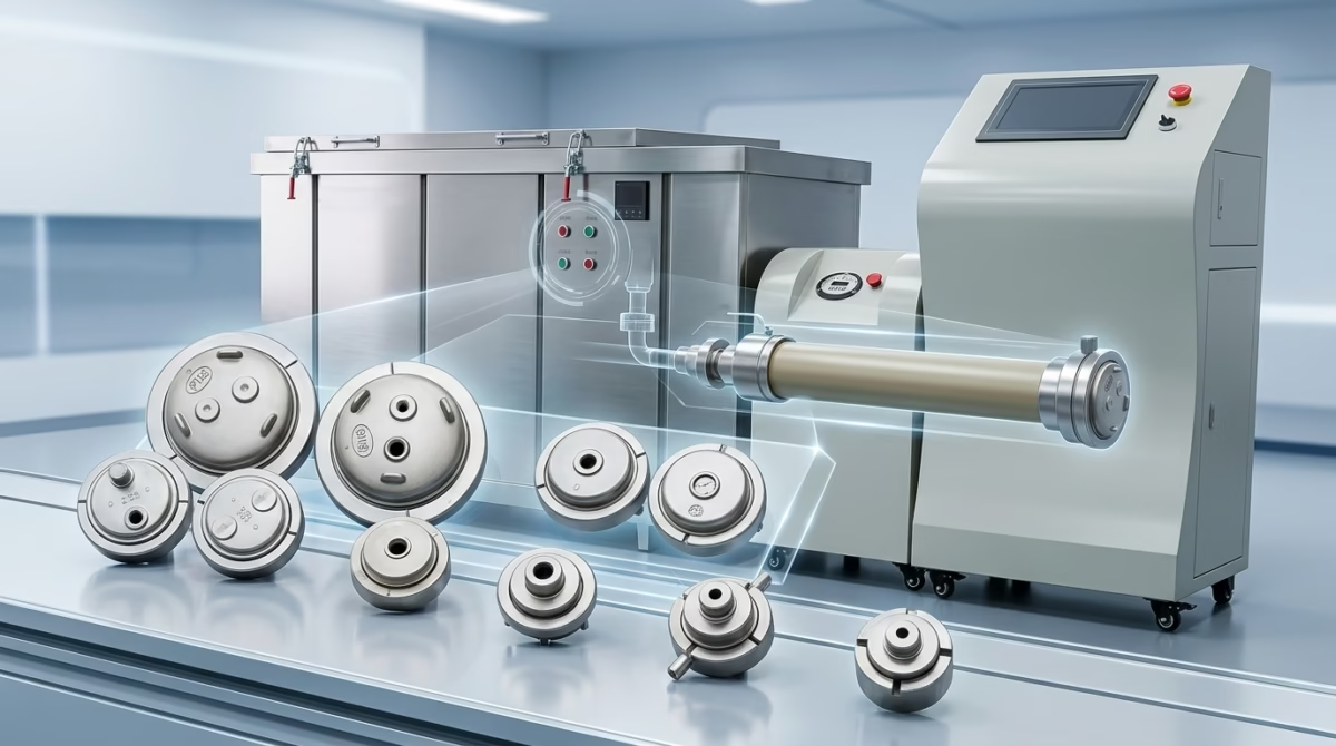
The standard is split into four parts. Part 1 gives the general method — apparatus, procedure and test report. Parts 2, 3 and 4 cover preparation of the three test piece types: pipe, component and assembly. An extruded pipe section and an injection-moulded fitting follow different preparation rules but the same general method. [2] [3] [4]
The first edition of Part 1, published in February 2006, replaced the earlier single-part ISO 1167:1996. It was last confirmed after systematic review in October 2021, so ISO 1167-1:2006 remains the current edition. [1]
One boundary is worth stating plainly. ISO 1167 measures resistance to internal pressure. It says nothing about resistance to external soil and traffic loading, which is the domain of ring stiffness testing, and nothing about impact resistance or raw material quality.
The Three Test Environments
ISO 1167 accommodates three media combinations, and the product standard dictates the choice. [1]
| Environment | Specimen filled with | Specimen surrounded by | Typical use |
| water-in-water | Water | Temperature-controlled water bath | Most common; long-term tests up to 1,000 h or more |
| water-in-air | Water | Temperature-controlled air oven | Where immersion is impractical or apparatus design requires it |
| water-in-liquid | Water | Another liquid | Rare; used where a specific medium must be replicated |
A water bath brings a specimen to temperature faster and holds it more uniformly than an oven, which is why long-term qualification work normally runs water-in-water. Changing the environment can change the time-to-failure even at identical pressure and temperature, so the environment always belongs in the report.
Apparatus: End Caps, Bath and Instrumentation
End caps — the decision that quietly changes the answer
ISO 1167 specifies two end cap types, and confusing them is one of the most consequential mistakes in pressure testing. [1]
| Type A | Type B | |
| Axial thrust | Transmitted to the test piece | Absorbed by external tie rods |
| Specimen loading | Free length carries the full end thrust | Free length carries hoop stress only |
| Wall condition | Realistic, but can buckle thin or hot specimens | Suppresses buckling due to thermal expansion |
| When required | Long-term strength testing referenced by ISO 9080 | Routine screening, large-diameter test pieces |
The practical rule: Type A end caps must be used when the result will feed an ISO 9080 long-term strength extrapolation, because ISO 9080 assumes the end thrust acts on the specimen. Where a pipe is large in diameter or tested hot, the axial load combined with thermal expansion can make the free length bow — Type B tie rods exist to remove that variable. Results from a Type A and a Type B rig are not interchangeable, and the type used always belongs in the report.
End caps must also allow the specimen to be purged of air before pressurisation, and any surface touching the pipe’s outer wall must have rounded edges — a sharp contact point creates a stress concentration that will produce a failure the pipe did not deserve. [1]
Bath, oven and measurement
ISO 1167 specifies water tank tolerance of ±1 °C for the general method; product standards that reference it commonly impose ±2 °C on the test temperature. [1] Ancillary instruments must be fit for the tolerance being claimed:
- Dimension gauges for outer diameter and wall thickness, compliant with ISO 3126 — wall thickness must be the minimum measured value, not the average, because the pressure calculation runs on it. [5]
- Calibrated pressure gauges whose range covers the target pressure rather than merely reaching it.
- A timer with 0.5 % accuracy and automatic stop on leakage or burst. [1]
- Suspension or support that keeps specimens off the tank walls and clear of each other. [1]
A multi-station rig typically shares one pressure source and one bath across many specimens, with independent stations letting individual specimens fail without disturbing the rest.
Test Piece Preparation
Part 2 governs pipe test pieces, and the dimensional rules are the part most often got wrong. [2]
| Parameter | Requirement |
| Free length between end caps | Minimum 3 × nominal outside diameter dₙ |
| Absolute minimum | 250 mm |
| Exception for DN > 315 mm | Free length may be shortened to 2 × dₙ if 3 × dₙ cannot be achieved |
| Injection-moulded tubular pieces | 25 mm ≤ dₙ ≤ 110 mm; l₀ = 3dₙ for dₙ < 50 mm; fixed minimum 140 mm for dₙ ≥ 50 mm |
| Total length | Must reserve space for thermal expansion if Type B end caps are used |
Free length is the length between the end caps, not the length of the cut pipe — the end cap insertion depth adds to the physical length you need to cut. Cutting and machining must remove all surface grease, dust and contamination, and all critical dimensions are measured and recorded before assembly. [2]
Specimens with longitudinal fusion lines are usable for comparative research but not recommended for formal material qualification, because moulding parameters strongly influence the internal stress distribution. [2]
The Test Procedure, Step by Step
- Prepare the test piece. Cut or machine to the required dimensions per Part 2, 3 or 4; clean the surfaces; measure and record outer diameter and minimum wall thickness. [2]
- Assemble the end caps and purge air. Fit the specified Type A or Type B caps, fill with water at or below the test temperature, and vent all trapped air. Residual air is not a minor nuisance — it cushions the specimen, distorts the pressure reading and is an energy-storage hazard. [1]
- Condition. Submerge or place the sealed specimen in the temperature-controlled environment for the mandatory minimum conditioning period, set by wall thickness. [1]
- Raise the pressure. Bring the specimen slowly to the calculated target pressure — a ramp of roughly 30 seconds to 1 hour — with the timer reset once stable target pressure is reached. [1]
- Hold at constant pressure and temperature. Maintain both continuously and observe for leakage and deformation throughout. [1]
- Terminate and record. Stop the timer and record elapsed time on rupture or leakage, noting failure location and mode. If the required duration completes with no leakage, the test ends as a pass. [1]
ISO 1167 Hydrostatic Pressure Test Procedure & Failures
Calculating the test pressure
Where the product standard specifies a circumferential (hoop) stress rather than a pressure, the hydrostatic pressure test on pipe runs at a pressure derived from the thin-wall relationship:
where p is the test pressure, σ the specified hoop stress, e_min the minimum measured wall thickness and d_n the nominal outside diameter.
Two consequences follow. Using nominal wall thickness instead of minimum measured wall thickness under-pressurises the test and can produce a false pass. And because SDR is the ratio of dₙ to nominal wall thickness, a higher SDR — a thinner-walled pipe in the same diameter — demands a lower pressure for the same hoop stress. [1]
Short-Term vs Long-Term: Where the Burst Test Fits
ISO 1167 covers short and long duration testing, but the two answer different questions, and conflating them is how a one-hour screening result gets mistaken for a material rating.
| Short-term | Long-term | |
| Typical duration | 1 hour, or up to about 100 h | 165 h, 1,000 h or longer |
| Typical temperature | Ambient, commonly 20 °C | Elevated, commonly 80 °C |
| Typical hoop stress | High — drives the specimen toward rupture | Low — deliberately below the failure threshold |
| What it detects | Gross manufacturing defects, wall faults, process excursions | Material grade and long-term strength |
| Where it sits in QA | Batch release testing | Type approval, MRS determination |
| Feeds what | Pass/fail on the batch | Time-to-failure data for ISO 9080 extrusion |
The short-term hydrostatic pressure test on pipe is the one that produces a burst. High hoop stress at ambient temperature drives the specimen to rupture within a working shift, which is what a production line needs for batch release, and it is the configuration most people have in mind when they ask for a pipe burst test under ISO 1167. ASTM D1599 describes that method; ASTM D1598 covers the constant-pressure time-to-failure method used for long-duration work. [6] [7]
Long-term testing runs at a deliberately low hoop stress, so anything that fails is a material or process problem rather than an expected over-stress. Results from several temperatures across several stress levels feed ISO 9080, which extrapolates a 50-year strength and yields the MRS value that becomes the pipe’s pressure class. [8] This is also the only configuration where ISO 1167 requires Type A end caps.
Failure Criteria and the Three Failure Modes
This is the part of ISO 1167 that separates a usable report from a worthless one.
A test piece passes if it survives the full specified duration at the specified temperature and pressure with no leakage, rupture or deformation beyond the defined limit. Anything else is recorded as a failure unless it can be attributed to the apparatus rather than the pipe. [1]
Failures divide into three modes, and only two of them are pipe failures. [9]
| Mode | Appearance | Usual cause | Validity |
| Type A — ductile burst | Wall tears and deforms; visible yielding | Specimen over-stressed relative to its wall thickness and grade | Valid failure — record; at high stress this can be the expected outcome |
| Type B — brittle fracture | Clean crack with no visible deformation; sudden, often at low stress | Degraded material, stress-cracking environment, voids, low antioxidant content, excessive internal stress | Valid failure — record and investigate; at low hoop stress this is the finding that matters |
| Type C — end cap or fitting failure | Leak or break at the pipe ends | Wrong end cap, insufficient sealing, contact stress from sharp edges | Invalid — retest with correct end caps |
The distinction between A and B carries real engineering weight. A ductile burst at high stress confirms the specimen was overloaded and the pipe behaved as a plastic material should. A brittle fracture at low stress is the signature of a material problem — often insufficient antioxidant, molecular degradation or internal stress frozen in during extrusion — and it should stop a batch, not merely mark it failed.
Type C is the reason the failure location must always be reported. A laboratory reporting “failed at 340 hours” without saying where cannot tell you whether this was a pipe problem or an end cap problem. Ask for the failure location and the failure mode, not just the time.
Reading an ISO 1167 Test Report
A complete report lets a third party reproduce the test without asking a question. It states the standard and part with editions, the end cap type, the test environment, the temperature and tolerance, the number of test pieces, the SDR or size, the test pressure and the hoop stress, the duration and failure criteria, the measured minimum wall thickness, and — critically — the failure location, failure mode and individual elapsed times rather than an average. [1]
Where ISO 1167 Sits Among Pipe Standards
| Standard | Covers | Relationship to ISO 1167 |
| ISO 1167-1 | General method for internal pressure resistance | The method itself |
| ISO 1167-2 / -3 / -4 | Preparation of pipe / component / assembly test pieces | Normative references of Part 1 |
| ISO 3126 | Determination of dimensions of plastics components | Supplies the measurement method for diameter and wall thickness |
| ISO 9080 | Extrapolation of long-term hydrostatic strength | Consumes ISO 1167 data; requires Type A end caps |
| ASTM D1598 | Time-to-failure under constant internal pressure | US counterpart to the long-duration case |
| ASTM D1599 | Resistance to short-time hydraulic pressure | US counterpart to the short-term burst case |
| ASTM D2837 | Obtaining a hydrostatic design basis | US equivalent role to ISO 9080 |
| GB/T 6111 | Resistance to internal pressure, Chinese national standard | Non-equivalent adoption of ISO 1167-1 to -4 |
| GB/T 15560 | Short-time hydraulic failure and constant-pressure resistance | Chinese counterpart to ASTM D1599 / D1598 |
GB/T 6111 is the standard you will meet most often on Chinese-made pipe documentation, and it adopts the four parts of ISO 1167 non-equivalently. [10] If you are comparing a Chinese test report against a European one, the hoop stress, temperature, duration and end cap type are the four fields to line up first.
The Equipment Behind the Test
The rig determines whether the result is defensible, because the tolerance of the apparatus caps the tolerance of the test. The core instrument is the hydrostatic pressure tester — a multi-station machine with independent pressure control per station, a temperature-controlled tank holding ±1 °C, calibrated pressure sensors, automatic stop on leakage or burst, and continuous logging of set and actual pressure, temperature and elapsed time.
BRT Testing’s pipe hydrostatic pressure tester covers multi-channel testing in MPa, PSI and bar across DN16 to DN1600, for PE, PVC, PP-R, PE-RT and composite pipes, and is specified against ISO 1167 alongside ASTM D1598, ASTM D1599, GB/T 6111 and GB/T 15560 — the same standard set this article walks through.
A hydrostatic result rarely stands alone, and the surrounding equipment usually shares the same sample set:
- Ring stiffness and flexibility testing machine — the ISO 9969 external-load counterpart, for the SN class ISO 1167 cannot tell you.
- CNC drop weight impact tester — ISO 3127 / ASTM D2444 external impact resistance.
- Melt flow index tester — ISO 1133 MFR, the compound consistency check behind many a marginal result.
- Carbon black content tester — ISO 6964, relevant when a brittle fracture points at dispersion or UV stabilisation.
- Differential scanning calorimeter — ISO 11357 oxidation induction time when antioxidant depletion is suspected.
For the full standard map across these methods, see our plastic pipe testing standards guide, which covers how ISO 1167, ISO 9969 and ISO 1133 fit together. Test parameters and tolerances for the wider range are on the test parameter reference page.
Frequently Asked Questions
What is an ISO 1167 hydrostatic test used for?
It determines the resistance of a thermoplastics pipe, fitting or assembly to internal hydrostatic pressure at a given temperature. The result supports two very different purposes: short-term batch release, where high stress drives the specimen to burst and reveals manufacturing defects, and long-term material qualification, where low stress at elevated temperature produces the time-to-failure data that ISO 9080 extrapolates into a 50-year strength rating.
How long does ISO 1167 testing take?
The duration is set by the product standard, not by ISO 1167. Short-term tests typically run one hour at ambient temperature to produce a burst. Long-term tests commonly run 165 hours, 1,000 hours or longer at elevated temperature, and are normally scheduled as type-approval work rather than batch testing. Conditioning time before pressurisation is separate and depends on wall thickness.
What is the difference between Type A and Type B end caps in ISO 1167?
Type A end caps are connected to the test piece but not to each other, so the hydrostatic end thrust is transmitted to the pipe and the free length carries the full axial load. Type B end caps are linked by external tie rods that absorb that thrust, so the specimen sees hoop stress only. Type A is required when results feed an ISO 9080 extrapolation.
What is the minimum free length of an ISO 1167 test piece?
The free length between end caps must be at least three times the nominal outside diameter, with an absolute minimum of 250 mm. For pipes with a nominal diameter above 315 mm where that cannot be achieved, a shortened free length down to two times the nominal diameter is permitted. Injection-moulded tubular pieces follow separate rules.
What is the difference between an ISO 1167 hydrostatic test and a pipe burst test?
They are the same family of test run under different conditions. A short-term hydrostatic pressure test on pipe deliberately over-stresses the specimen so that it bursts, which is what batch release testing needs. A pipe burst test to ISO 1167 run at low hoop stress for 165 hours or more instead characterises the material rather than screening the batch. ASTM D1599 describes the short-time method; ASTM D1598 describes constant-pressure time-to-failure.
How do I calculate the hydrostatic test pressure for a plastic pipe?
Multiply twice the specified hoop stress by the minimum measured wall thickness, then divide by the difference between the nominal outside diameter and that minimum wall thickness. The result is the internal pressure needed. Two points decide accuracy: use the minimum measured wall thickness rather than the nominal value, and remember that a higher SDR, meaning a thinner wall in the same diameter, needs a lower pressure.
What do ductile and brittle failures mean in ISO 1167 testing?
A ductile burst shows wall tearing and visible deformation, and is the expected outcome when a specimen is deliberately over-stressed — so it is normally a valid result. A brittle fracture is a clean crack with no visible deformation and often occurs at low stress. That pattern points to material problems such as voids, oxidation or excessive internal stress, and it warrants investigation rather than a simple pass mark.
Can a pipe pass ISO 1167 and still fail in service?
Yes. ISO 1167 measures resistance to internal pressure only. It does not evaluate resistance to external soil and traffic loading, which ring stiffness testing covers, nor impact resistance, nor long-term environmental stress cracking under field conditions. A pipe can hold its pressure rating perfectly in the laboratory and still fail from installation damage, external loading or a slow crack growth mechanism the test was never designed to detect.
Conclusion — How to Read a ISO 1167 Hydrostatic Test Result
Work through these five steps in order, and most misleading pressure results sort themselves out:
- Confirm the standard and part. ISO 1167-1 for the method, plus the product standard that set your temperature, stress and duration.
- Confirm the end cap type. Type A or Type B changes how the specimen was loaded and therefore what the result means.
- Confirm the specimen dimensions. Minimum measured wall thickness, SDR and free length must all be in the report.
- Confirm the failure location and mode. A wall failure is data. A fitting failure is a retest. A ductile burst at high stress and a brittle fracture at low stress mean opposite things.
- Confirm what the result is allowed to claim. A one-hour batch test releases a batch. It does not establish a 50-year rating.
If you are specifying a hydrostatic pressure test rig, or working out whether an existing result can support the pressure class you intend to publish, get in touch with our technical team — see the plastic pipe testing equipment range or read more about us.
About the author — BRT Testing Technical Content Team Shenyang Baoruitong Automation Equipment Co., Ltd. designs and supplies plastic pipe testing equipment including hydrostatic pressure testers, ring stiffness frames, impact testers and melt flow index testers for pipe and compound manufacturers worldwide. This guide was compiled by the company’s technical content team from the published texts and normative references of ISO 1167-1:2006 and from commissioning work on multi-station pressure rigs. Equipment specifications are quoted from BRT Testing’s published product pages. Last reviewed September 2026.