- The Short Answer
- Why Coatings Need a Furnace at All
- The Heating Curves the Furnace Runs
- What Happens Inside During a Coated-Section Test
- The Small-Scale Alternative: ASTM D3806
- Choosing and Specifying a Coating Test Furnace
- What a Full Coating Furnace Campaign Involves
- Frequently Asked Questions
- Is a coating test furnace the same as a fire resistance furnace?
- Why can’t a small burner test replace the furnace?
- What does EN 13381-8 add to the furnace test?
- What is the ASTM D3806 two-foot tunnel used for?
- Which fire curve applies to intumescent coatings?
- How is coating thickness decided from furnace data?
- Does the coating rating transfer between steel sections?
- Conclusion: A Decision Order
- About the Author
- Sources
The Short Answer
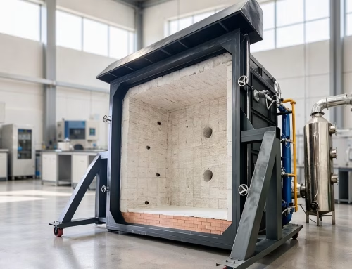
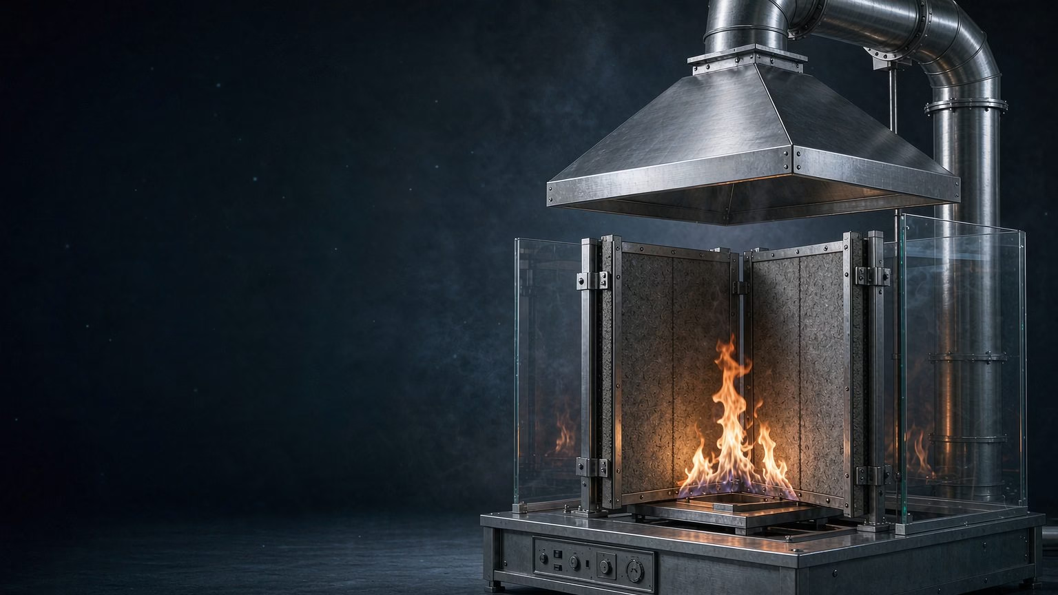
A fire retardant coating test furnace is a furnace that evaluates a coated construction against the standard fire curve, rather than a small flame against a coated plate. Thin-film intumescent and thick-film cementitious coatings ultimately earn their ratings in furnace tests: a loaded steel section or an assembly, coated at a declared thickness, is exposed to a controlled heating regime — the cellulosic curve of ISO 834 / EN 1363-1 or, for tunnels and offshore work, hydrocarbon curves — and the furnace time at which steel temperature or assembly criteria are exceeded becomes the coating system’s rating 123. Small-scale apparatus such as the ASTM D3806 two-foot tunnel screens paints before that investment, but it does not produce a fire resistance rating 4.
Why Coatings Need a Furnace at All
A coating’s job is to slow heat reaching the substrate. Bunsen-burner and cone-heating tests can measure ignition, flame spread and heat release of the coating film itself — and they matter — but none of them reproduces the question a structural fire design actually asks: how long does this protected member stay below its critical temperature in a compartment fire? That question has three ingredients only a furnace can supply:
- a regulated furnace temperature following a defined time-temperature curve, so results are comparable between laboratories and years;
- a real substrate — a steel column or beam with its actual section factor, not a flat plate — because heat uptake depends on the mass and perimeter of the section as much as on the coating;
- a mechanically realistic state, most importantly the load on the member, since deformation and coating adhesion under load change the failure mode.
This is why coating approvals read like “1,110 g/m² dry film thickness gives R 60 on a section factor up to 250 m⁻¹” — each line of such a table traces back to furnace data (see the companion article on fire retardant coating testing methods and equipment for the full method landscape, and on the difference between fire retardant and fire resistant coatings for the vocabulary).
There is also a scaling argument. A coating film on a small plate can be heated uniformly by a cone or a radiant panel, but a structural section in a compartment fire receives heat from a furnace atmosphere whose temperature, emissivity and pressure all evolve together for an hour or more. Intumescent char grows, cracks and re-densifies over that timeline; its insulating value at minute 40 is not predictable from its behaviour in the first two. Furnace exposure is the only laboratory environment that forces the coating through that whole timeline under controlled, repeatable conditions — which is why every framework that assigns structural ratings, EN or ASTM, routes the final decision through a furnace.
The Heating Curves the Furnace Runs
The cellulosic curve
The default exposure for building products is the cellulosic (standard) fire curve, defined in ISO 834-1 and adopted for European fire resistance testing by EN 1363-1:
T = 20 + 345 × log10(8t + 1) (T in °C, t in minutes)
Working from that equation: about 842 °C at 30 minutes, 945 °C at 60 minutes, 1,006 °C at 90 minutes and 1,049 °C at 120 minutes [2]. The current edition is ISO 834-1:2025, in force since 30 May 2025, which replaced the 1999 edition the same day [2].

EN 1363-1:2020 adds the laboratory requirements around the curve — furnace pressure control, thermocouple types and placement, and the rules for recording failure [1]. A furnace does not simply follow the curve on paper: EN 1363-1 defines how closely the furnace control must track the target temperature and how deviations are recorded, which is why the furnace log is part of every coating test report. Laboratories comparing results across years should check which edition each historical campaign was run under, because the 2025 re-issue is recent enough that older reports predate it.
Hydrocarbon and tunnel curves
Where the fire risk is a fuel spill or a tunnel fire, coatings are evaluated against faster, hotter exposures. EN 1363-2 defines the alternative and special curves — the hydrocarbon curve among them — that run far above the cellulosic values in the first minutes [3]. Coatings qualified for petrochemical or tunnel applications are therefore usually furnace-tested twice: once cellulosic, once hydrocarbon, because intumescent char behaviour differs sharply between the two regimes.
What Happens Inside During a Coated-Section Test
The specimen
For structural coatings, the specimen is a steel section — commonly a column or beam representative of the product’s intended use — coated at the dry film thickness (DFT) under assessment. The section’s heated perimeter to cross-sectional area ratio (section factor, A/V or Hp/A) is recorded, because it is the variable the assessment will extrapolate: compact sections heat slowly and need less coating, slender sections heat quickly and need more 5.
Specimen build is a quality gate in its own right. The coating must be applied with the manufacturer’s own system — primer, mesh if the datasheet requires it, and the declared number of coats — because the assessment covers the system, not the intumescent layer alone. Application records, DFT survey maps and curing logs travel with the specimen into the furnace file; a test whose coating application cannot be reconstructed is not repeatable, and repeatability is the whole point of a standardised furnace.
The instrumentation
Embedded and surface thermocouples track steel temperature at defined positions along the member; plate thermocouples in the furnace track the exposure; and for loaded tests, hydraulic actuators hold the design load throughout. Under EN 13381-8, the European assessment standard for reactive fire protection on steel members, the test data are processed into the relationship between coating thickness, section factor and achieved fire resistance — the format in which coating manufacturers publish their design tables [5]. The assessment framework sits within the structural fire design environment of the Eurocodes (EN 1992-1-2 for concrete structures and its steel-side companions), which consume those ratings in design 6.
The criteria
For a loadbearing coated member the failure criterion is the R criterion — loss of loadbearing capacity as the steel reaches its critical temperature under load. (How R ratings are structured across steel protection routes is covered in our guide to fire resistance testing for steel structures.) For separating assemblies coated with a protective product, E and I criteria apply instead, exactly as in any fire resistance test [1]. A coating test furnace therefore needs the same control and instrumentation chain as any fire resistance furnace; what distinguishes it is the specimen programme built around coating variables (DFT levels, section factors, application conditions).
The Small-Scale Alternative: ASTM D3806
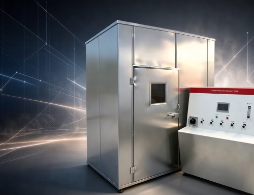
Before a manufacturer commits to full-scale furnace work, screening tests rank formulations cheaply. The long-established tool is ASTM D3806, the Small-Scale Evaluation of Fire-Retardant Paints (2-Foot Tunnel Method), current as the 2019 edition [4]. A coated panel faces a small gas-fired tunnel flame, and the method reports intumescence and flame spread performance on a laboratory scale. It is deliberately not a fire resistance test: a paint that performs well in the 2-foot tunnel has earned a screening result, not an R, E or I rating — the furnace campaign is still ahead of it.
That division of labour is a feature, not a limitation. Formulation screening lives on iteration speed: dozens of variants, small specimens, same-day results. Furnace work is the opposite — few variants, expensive specimens, and days of furnace time per cell. Laboratories that push formulation questions into the furnace waste budget; laboratories that skip screening and go straight to the furnace discover their worst formulations at the highest possible price per data point. The two scales are complementary, and the specification for each should say which job it is doing.
Choosing and Specifying a Coating Test Furnace
| Item | Why it matters for coating work |
|---|---|
| Furnace orientation | Vertical furnaces take columns and wall-mounted sections; horizontal furnaces take beams and floor-type assemblies |
| Section capacity | Must accept the section factors the design tables will claim; slender sections drive the largest specimens |
| Loading capability | Loaded-column testing is what R ratings on structural steel are built from [5] |
| Curve control | Cellulosic per EN 1363-1/ISO 834 [1][2] plus hydrocarbon capability if EN 1363-2 work is planned [3] |
| Thermocouple chain | Steel-embedded, plate and furnace thermocouples with the recording density EN 1363-1 expects [1] |
| Data processing | Section-factor ↔ DFT ↔ resistance analysis in line with EN 13381-8 [5] |
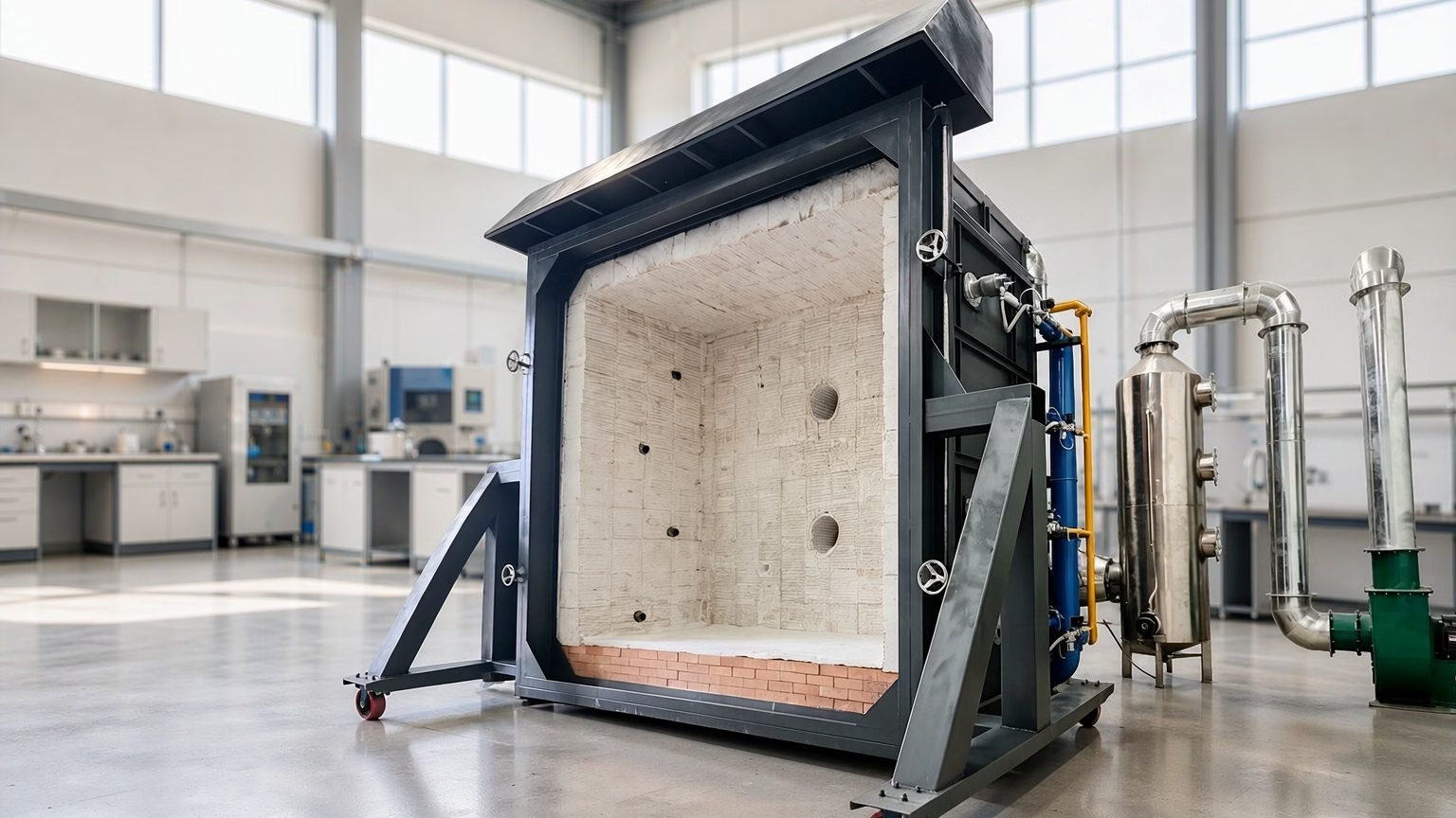
BRT Testing builds the steel fire retardant coating test furnace for exactly this programme, alongside vertical and horizontal fire resistance furnaces.
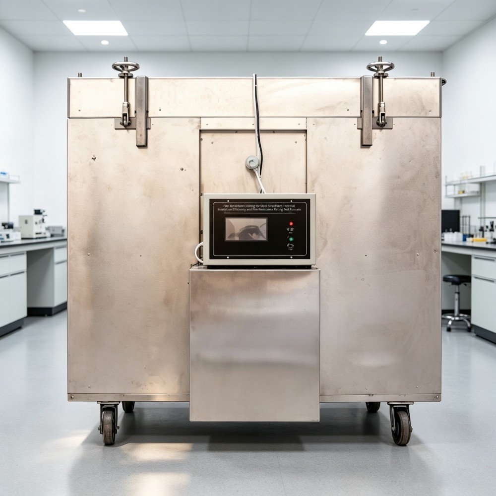
The steel fire retardant coating test furnace product page lists capacities and instrumentation, and the horizontal fire resistance test furnace page covers beam-scale work. For upstream characterisation of the coating film itself — heat release, ignition, smoke — the cone calorimeter complements the furnace.
What a Full Coating Furnace Campaign Involves
A coating qualification programme is planned as a matrix, not a single burn. Each claim line in the finished design table — a dry film thickness giving a rating up to a section factor — has to be anchored in furnace data, either directly or through the assessment’s permitted extrapolations. Laboratories therefore fix the matrix before the first burner lights, and every element of it is a decision that shapes the furnace days that follow:
| Campaign element | What gets fixed | Why it is fixed before the burn |
|---|---|---|
| DFT levels | The thickness points to test, usually spanning the intended range | Extrapolation beyond tested thicknesses is limited [5] |
| Section factor spread | Sections from compact to slender | Slender sections govern the worst case in the design table [5] |
| Conditioning | Application method, curing time, environment | Application conditions are part of the assessed system |
| Instrumentation | Steel, plate and furnace thermocouple positions | Positions are prescribed by EN 1363-1 [1] |
| Pass criteria | Target R (or E/I) duration per cell | Criteria decide when the burn stops, not operator judgement [1] |
| Verification | DFT measured on the specimen before testing | Unverified thickness voids the claim line |
Dry film thickness verification deserves emphasis: coating thickness on a rough steel section varies across the surface, and magnetic or ultrasonic gauges used before the test are what make the reported DFT defensible. A furnace result on an unmeasured coating is an anecdote, not a data point.
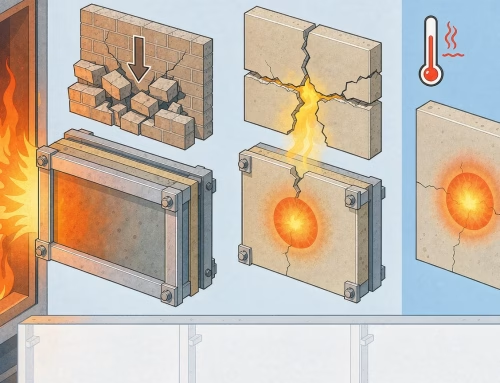
Failure modes the furnace exposes
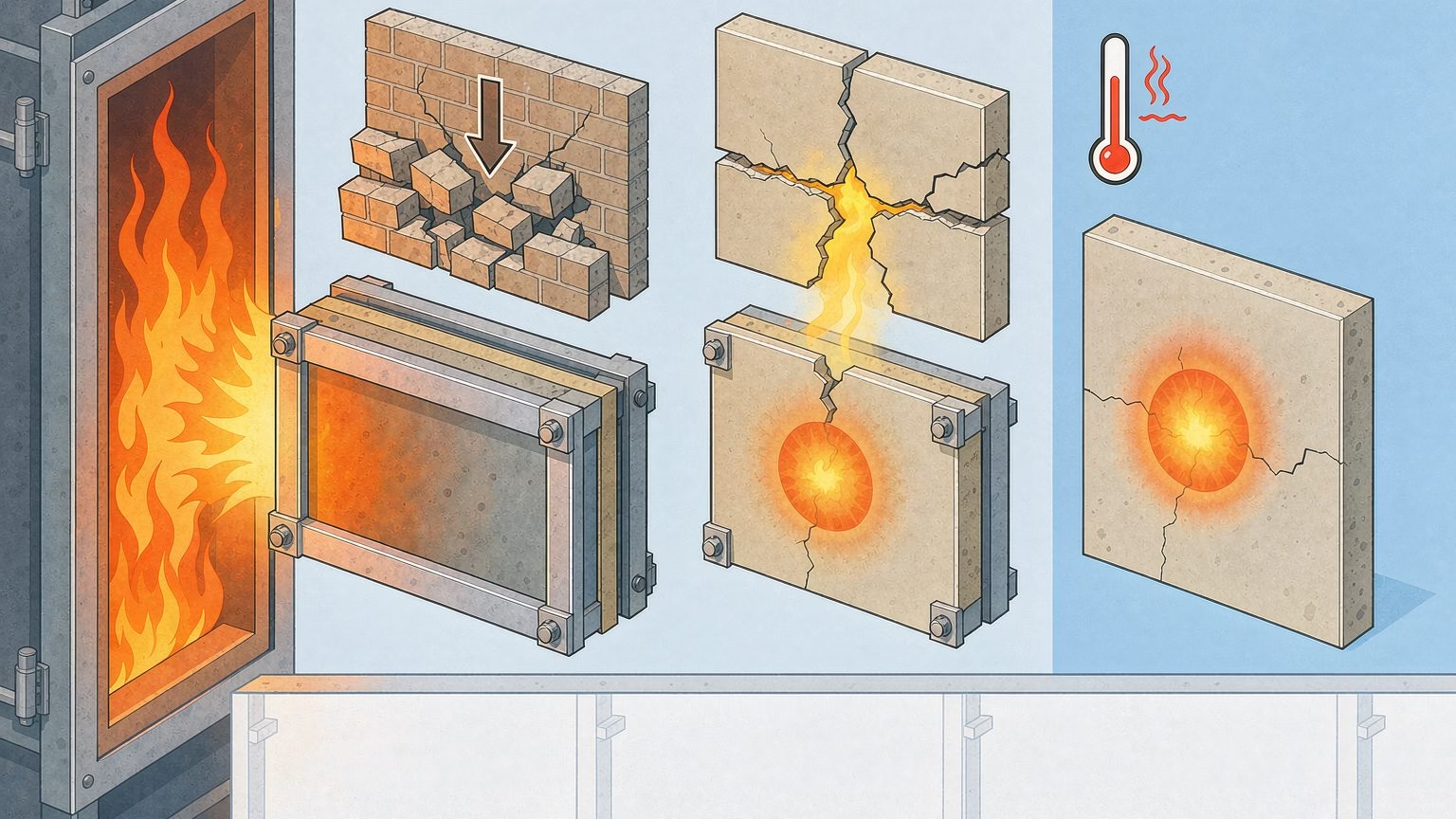
Furnace work is where coating systems reveal the weaknesses that bench tests smooth over. The recurring patterns are well known to coating laboratories:
| Observation in the furnace | What it usually indicates | Design consequence |
|---|---|---|
| Char shrinkage or cracking early in the burn | Intumescent formulation or application fault | Rating collapses well before the target duration |
| Delamination or coating fall-off under load | Adhesion to the substrate insufficient, often load-dependent | Claim must be restricted to the tested load or application system |
| Thin spots reaching steel temperature first | Uneven DFT application | Thickness verification and application QC become part of the system |
| Excessive expansion into the furnace hardware | Over-application or clearance design issue | Clearances and maximum DFT get recorded in the field of application |
Each of these is recorded in the test report and feeds the assessment: the difference between a coating system with a clean data set and one carrying caveats is often visible in the first thirty minutes of the first burn.
From results to the design table
After the campaign, the results are processed under EN 13381-8 into the relationship the market actually buys: thickness against section factor against achieved resistance [5]. The assessment also fixes how far the data may be extended — to untested section types, to intermediate thicknesses, to other steel grades — and every one of those extensions carries documented limits. Specifiers reading a coating datasheet are therefore reading the compressed output of a furnace campaign plus an assessment chain, which is why a datasheet without section-factor and DFT references cannot be evaluated at all.
Frequently Asked Questions
Is a coating test furnace the same as a fire resistance furnace?
Functionally yes — the coating work is a fire resistance furnace programme whose specimen matrix varies coating thickness and section factor. The furnace itself must meet the same EN 1363-1 or ASTM E119 requirements for temperature control, pressure and instrumentation as any fire resistance test. What makes it a “coating” furnace is the test plan built around it: coated sections, DFT verification and the EN 13381-8 style assessment of results.
Why can’t a small burner test replace the furnace?
A burner test measures the coating film’s reaction to a small flame, but a coating’s job is to protect a loaded structural member for tens of minutes in a fully developed fire. Steel temperature under load, section factor effects, char integrity and adhesion over long exposures cannot be reproduced on a plate in a burner cabinet. Small-scale tests screen formulations; only the furnace produces the R, E or I performance the design tables claim.
What does EN 13381-8 add to the furnace test?
EN 13381-8 is the assessment standard for reactive (intumescent) fire protection on steel members. It defines how results from furnace tests are processed into the relationship between dry film thickness, section factor and fire resistance, and how far those results may be extended to untested sections and thicknesses. Without that assessment step, individual furnace tests remain isolated data points rather than a usable coating design table.
What is the ASTM D3806 two-foot tunnel used for?
ASTM D3806 is a small-scale screening method for fire-retardant paints. A coated panel is exposed to a gas flame in a 2-foot tunnel apparatus, and the method evaluates intumescence and flame spread performance. It ranks formulations cheaply before furnace investment, but it does not produce a fire resistance rating — no R, E or I classification can come from it.
Which fire curve applies to intumescent coatings?
Building applications default to the cellulosic curve of ISO 834 / EN 1363-1, reaching about 842 °C at 30 minutes and 945 °C at 60 minutes. Hydrocarbon exposures defined in EN 1363-2 are used for petrochemical, tunnel and offshore applications, and they are considerably more severe in the first minutes. Coatings for those markets are usually qualified under both curves because intumescent char behaves differently in each.
How is coating thickness decided from furnace data?
Furnace results map dry film thickness and section factor to achieved fire resistance. The EN 13381-8 assessment processes the tested combinations and extends them within limits to untested sections, yielding the design tables coating manufacturers publish — typically “X g/m² DFT for R 60 up to section factor Y”. A specifier reads the required rating and section factor off the member and takes the corresponding thickness from that table.
Does the coating rating transfer between steel sections?
Only within the assessed limits. A result on one section at one DFT is extended to other sections through the EN 13381-8 assessment, which defines how section factor, steel type and thickness variations may be covered. A section outside the assessed envelope, or a different application condition, needs new data. This is why coating datasheets always state the section factor range each thickness line applies to.
Conclusion: A Decision Order
If you are setting up or specifying coating fire testing, the order is fixed:
- Screening — cone calorimeter and tunnel-scale work (ASTM D3806) to rank formulations [4].
- Furnace campaign — cellulosic curve first, hydrocarbon where the market requires it [1][2][3].
- Assessment — process results into the DFT / section-factor / rating table under EN 13381-8 [5].
- Design consumption — Eurocode fire parts apply the tables in structural design [6].
Two habits keep step 2 affordable. Fix the specimen matrix (DFT levels, section factors, conditioning) before the first burn, so every furnace day produces a claim line. And insist on DFT verification records for every specimen, because an unverifiable thickness quietly deletes the value of an otherwise clean test. A fire retardant coating test furnace is a capital decision, but its output quality is decided on paper — in the test plan — long before the burners light.
BRT Testing supplies the furnace line for step 2 — start at the steel fire retardant coating test furnace product page or contact us with your section-factor envelope and target ratings.
About the Author
BRT Testing (Shenyang Baoruitong Automation Equipment) manufactures fire test furnaces, cone calorimeters and smoke instrumentation for laboratories and coating producers. The BRT Testing content team writes from the equipment side of the coating qualification chain — furnace control, instrumentation and the assessment data that turn test days into design tables. References above point to the current editions of ISO 834-1, EN 1363-1/-2, EN 13381-8 and the relevant ASTM methods.
Sources
- UNI — EN 1363-1:2020 (Status CURRENT, 19 Feb 2020) — https://webstore.uni.com/en/en-1363-1-2020
- UNI — ISO 834-1:2025 (Status CURRENT, 30 May 2025) — https://webstore.uni.com/en/iso-834-1-2025
- UNI — EN 1363-2:1999 (Status CURRENT, 18 Aug 1999) — https://webstore.uni.com/en/en-1363-2-1999
- ASTM International — D3806-19, Small-Scale Evaluation of Fire-Retardant Paints (2-Foot Tunnel Method) — https://store.astm.org/d3806-19.html
- UNI — EN 13381-8:2013 (Status CURRENT) — https://webstore.uni.com/en/en-13381-8-2013
- UNI — EN 1992-1-2:2023 (Status CURRENT) — https://webstore.uni.com/en/en-1992-1-2-2023