- What ISO 179 and ISO 180 Actually Measure
- The Geometry of ISO 180 Izod Testing
- ISO 179 Charpy Specimen Geometry and the 2026 Table 1 Correction
- Preparation, Conditioning and the Clamping Force Nobody Records
- Selecting Pendulum Energy: The 10–80 % Rule
- Reading a Plastic Impact Test Result: Formula, Failure Type and Significant Figures
- When a Plastic Impact Test Result Is Not Comparable
- Where ISO 179 and ISO 180 Sit in the Standards Landscape
- What Changed in the 2026 Edition of ISO 179 Charpy Testing
- Choosing ISO 179 Charpy and ISO 180 Izod Equipment
- Frequently Asked Questions
- Is ISO 179 the same as Charpy, and ISO 180 the same as Izod?
- What is the main difference between Charpy and Izod testing?
- Which edition of ISO 179-1 is current?
- Why do I get a different impact result from a different laboratory?
- Can one machine run both Charpy and Izod tests?
- Why does my specimen not break, and can I still report a value?
- What should a plastic impact test report contain?
- Conclusion: A Four-Step Decision Sequence
ISO 179 is the Charpy method for plastics and ISO 180 is the Izod method. Both measure the energy a rigid-plastic specimen absorbs when a pendulum breaks it in a single blow, and both report it in kilojoules per square metre. The two numbers are not interchangeable.
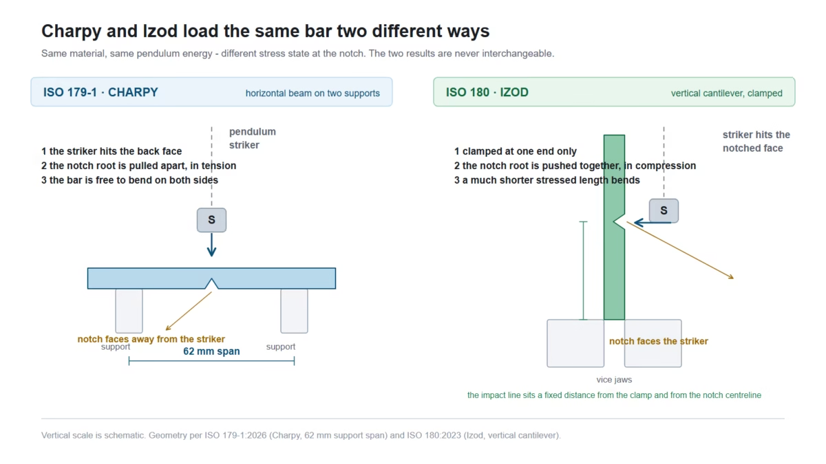
The difference is where the bar sits and which face the striker hits. In Charpy (ISO 179-1) the bar lies on two supports and is struck at mid-span on the face opposite the notch 15. In Izod (ISO 180) the bar stands vertically as a cantilever and is struck on the face containing the notch 6.
Start with Charpy: ISO 10350-1 treats ISO 179-1 as the preferred impact method for datasheet single-point data 14, and Charpy has the wider material applicability 1. Add Izod when a customer specification asks for it by name.
What ISO 179 and ISO 180 Actually Measure
Both standards define an impact strength: the energy absorbed in breaking a specimen, normalised by the original cross-sectional area. ISO 180 names the unnotched value aiU and the notched value aiN — the second referred to the cross-section at the notch — and expresses both in kJ/m² [6].
Why the result is an energy index, not a stress
The striker passes through the specimen in a fraction of a millisecond, so there is no time to record a stable load; the only dependable measurement is the energy the pendulum loses. Dividing by the cross-section is what makes specimens of different thickness comparable. Neither standard offers design data — ISO 180 states the method “is not intended to be used as a source of data for design calculations” [6], and ISO 179-1 claims only to estimate brittleness or toughness “within the limitations inherent in the test conditions” [1]. An impact value ranks materials and batches; it is not a stress for a model.
The Geometry of ISO 180 Izod Testing
Izod’s defining feature is the cantilever. ISO 180 defines the principle as a specimen “supported as a vertical cantilever beam”, broken by a single striker blow, with the line of impact a fixed distance from the clamp and — for notched specimens — from the centreline of the notch [6].
Which face the striker hits
ISO 180 states that the notched Izod value is measured “with the pendulum striking the face containing the notch” [6]. Charpy is the mirror image, striking the unnotched back so that the notch root is loaded in tension — so turning a specimen round in an Izod vice is not a small error, but a different test.
The direction of blow must also be reported for anisotropic materials.
| Designation | Meaning | Typical use |
|---|---|---|
e = edgewise |
Blow parallel to the specimen width b, striking the narrow edge | The standard Izod arrangement |
f = flatwise |
Blow parallel to the thickness h, striking the wide face | Sheet and plaque specimens |
p = parallel |
Blow parallel to the laminate plane | Long-fibre composites |
n = normal |
Blow normal to the laminate plane | Not usually used with Izod [6] |
loading geometry
ISO 179 Charpy Specimen Geometry and the 2026 Table 1 Correction
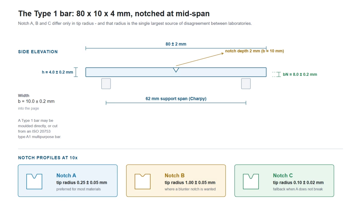
The reference bar is the same for both methods: 80 mm × 10 mm × 4 mm, supported over a 62 mm span in Charpy [1]. ISO 179-1 also defines Type 2 and Type 3 specimens for materials that fail by interlaminar shear, using a span expressed as a multiple of specimen thickness rather than a fixed 62 mm [1].
| Feature | ISO 179-1 (Charpy) | ISO 180 (Izod) |
|---|---|---|
| Reference specimen | Type 1, 80 × 10 × 4 mm | Type 1 (ISO 20753 A1 blank) |
| Support | Two supports, 62 mm span | Vertical cantilever clamp |
| Remaining width at notch base bN | 8.0 ± 0.2 mm | 8 mm ± 0.2 mm [6] |
| Notch A tip radius | 0.25 ± 0.05 mm | 0.25 ± 0.05 mm |
| Notch B tip radius | 1.00 ± 0.05 mm | — |
| Notch C tip radius | 0.10 ± 0.02 mm | — |
| Direction designation | e, f, n, p |
e, f, n, p [6] |
| Notch preparation | Machined per ISO 2818 or moulded | Machined per ISO 2818 or moulded |
The three ISO 179-1 notch types are not interchangeable. Notch A (0.25 mm tip radius) is preferred for most materials, notch B (1.00 mm) where a blunter notch is wanted, and notch C (0.10 mm) is the fallback when an A-notched specimen does not break [1]. Because the notch root decides where the crack starts, ISO 179-1 publishes a CCD-microscope method for confirming notch tip radius rather than a comparator alone [1].
iso179 iso180 specimen notch
What the ISO 179 Charpy 2026 edition corrected
ISO 179-1 was reissued in March 2026 as a fourth edition, replacing the 2023 third edition 3. The foreword records one technical change: “replaced the correct dimensions of specimen type 3 in Table 1” [1]. A laboratory still running the 2023 table therefore holds one wrong specimen dimension — a concrete reason to check the edition loaded in the instrument’s method library.
Preparation, Conditioning and the Clamping Force Nobody Records
Which preparation route applies is set by the material rather than by preference, and both standards point to the same moulding, machining and multipurpose-blank family [6][1].
| Stage | Reference | What it fixes |
|---|---|---|
| Conditioning atmosphere | ISO 291 | 23 °C / 50 % RH standard atmosphere |
| Compression moulding, thermoplastic | ISO 293 | Plaque and bar consolidation |
| Injection moulding | ISO 294-1 (ISO 294-3 in ISO 179-1) | Multipurpose and bar specimens |
| Compression moulding, thermoset | ISO 295 | Thermoset bars |
| Powder moulding compounds | ISO 10724-1 | PMC multipurpose specimens |
| Machining from sheet or product | ISO 2818 | Cut and machined geometries |
| Long-fibre test plates | ISO 1268-11 | Injection-moulded BMC and LFT plates |
| Multipurpose specimen | ISO 20753 | Type A1 source blank |
| Dimension measurement | ISO 16012 | How b, h and bN are determined |
Two measurement rules belong in the work instruction. Micrometers must resolve specimen dimensions to 0.02 mm, and the micrometer used for the remaining width bN must carry a 2 mm to 3 mm wide anvil profiled to fit the notch [6] — a flat-anvil micrometer cannot see the notch base, and the error it introduces is invisible in the result. Melt flow rate is the processing-side companion to impact toughness, covered by the ISO 1133 melt flow index procedure guide.
The rule almost nobody records is the clamping one: ISO 180 requires a means of standardising the Izod clamping force and requires that force to be reported [6]. Two laboratories running the same plastic impact test on different Izod rigs, one torqued and one hand-tightened, will report different numbers.
Selecting Pendulum Energy: The 10–80 % Rule
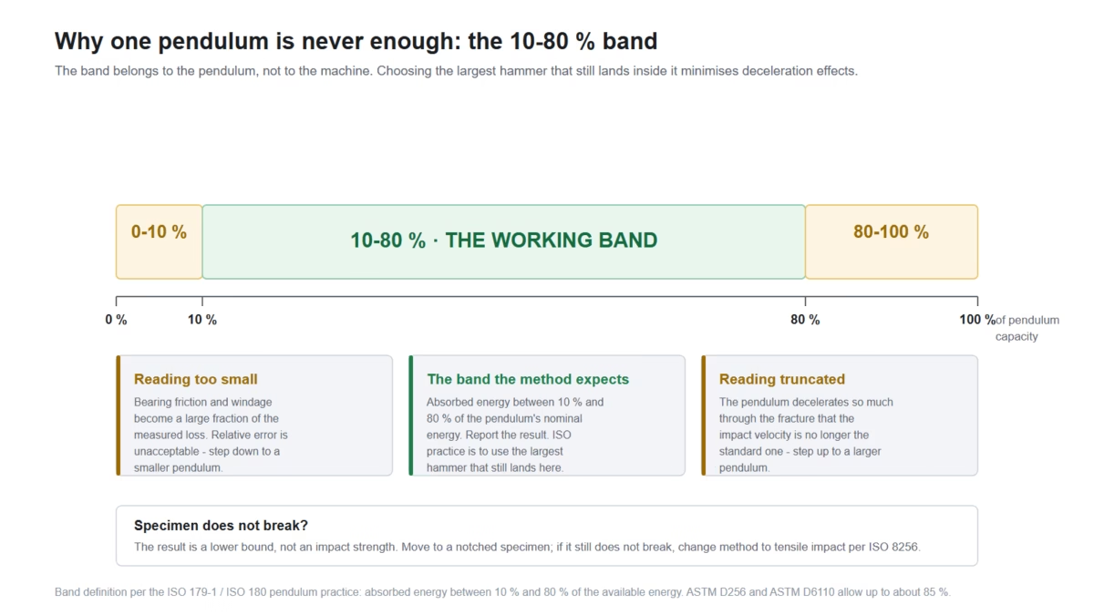
The pendulum’s energy capacity is not a “bigger is safer” choice. Traditional pendulum testers work in a band of 10 % to 80 % of the pendulum’s nominal energy [14]. Below 10 %, bearing friction and windage become a large fraction of the measured loss; above 80 %, the pendulum decelerates so much through the fracture that the impact velocity is no longer standard.
iso179 iso180 energy band
The band is why laboratories own several hammers
ISO practice is to choose the largest pendulum that still leaves the absorbed energy inside the window, which minimises deceleration effects [14]. Across a mixed material portfolio that means frequent hammer changes. An instrumented machine that records force against deflection has a much wider usable band per hammer, because it does not depend on matching the energy.
| Situation | What the result tells you | What to do |
|---|---|---|
| Absorbed energy < 10 % of capacity | Tare losses dominate; relative error unacceptable | Step down to a smaller pendulum |
| 10–80 % of capacity | The standard working band [14] | Report the result |
| > 80 % of capacity | Deceleration invalidates the impact conditions | Step up to a larger pendulum |
| Specimen does not break | Only a lower bound; no strength value | Use a notched specimen, or ISO 8256 tensile impact [14] |
Reading a Plastic Impact Test Result: Formula, Failure Type and Significant Figures
Two formulas cover the reporting. The unnotched impact strength divides the corrected absorbed energy by the original cross-section; the notched value divides the same energy by the cross-section remaining at the notch base. Using the full width in the denominator is the commonest arithmetic error in a notched report, and on a Type 1 bar it inflates the answer by roughly 20 %.
Failure type is reported alongside the number, because each code changes what the number means.
| Code | Failure mode | How the result is treated |
|---|---|---|
C |
Complete break — two or more separate pieces | Value reported |
H |
Hinge break — held together by a thin skin | Value reported |
P |
Partial break — incomplete fracture | Reported as a P result only |
N / NB |
No break — bending only, sometimes with stress whitening | No value; recorded as a non-break |
A batch can contain more than one failure mode, in which case the modes are reported separately rather than averaged. Results are rounded to two significant figures, and where failure types are mixed the median and the proportion of each type are given instead of a single mean [1].
Why “no break” has no value
A non-breaking specimen shows only that the absorbed energy exceeds what the pendulum could deliver, so the outcome is a lower bound rather than an impact strength. The route forward is defined rather than improvised: move to a notched specimen, and if it still does not break, change method to tensile impact per ISO 8256 [14].
When a Plastic Impact Test Result Is Not Comparable
Impact strength is unusually easy to measure inconsistently, and both standards say so. ISO 180 warns that specimens of different dimensions, notches or preparation conditions “may produce results which are not comparable”, and lists the apparatus energy capacity, impact velocity and conditioning state as further influences [6].
| Variable | Effect on the reported number |
|---|---|
| Notch tip radius (A to C) | Very large; a sharper notch concentrates stress and lowers the result |
| Machined vs moulded notch | Systematic; the two are not interchangeable |
| Absorbed energy outside 10–80 % | Error grows, or the impact conditions break down |
| Test temperature | Large; every polymer has a ductile-to-brittle transition region |
| Izod clamping force | Real for clamping-sensitive plastics; must be standardised and recorded [6] |
| Specimen thickness | Changes the plane-strain state and therefore the fracture mode |
| Fibre or filler direction | Parallel and normal blows differ on the same plaque |
Most impact specifications that matter are written at a temperature, not at ambient. Notched tests down to −70 °C are routine in accredited laboratories using a climate chamber or nitrogen cooling [15], and both standards condition specimens in the ISO 291 atmosphere before the blow [1][6]. The difficulty at low temperature is thermal rather than mechanical: the critical notch root must still be at the specified temperature when the striker lands, so the transfer time from the conditioning bath to the machine belongs in the work instruction.
A defensible record therefore names the standard and its year, the specimen type, the notch type, the impact direction letter, the pendulum energy, the test temperature, the conditioning state and the failure type [1]. A datasheet value is usable only when it carries the same qualifiers — for example “Charpy notched impact 40 J at −20 °C” — and is close to meaningless when it does not [15]. When a specimen breaks outside its expected failure mode, the remaining question is usually about composition, and the FTIR polymer identification workflow is the usual next step.
The instrumented variant: ISO 179-2
The instrumented Charpy method records a force-deflection or force-time diagram instead of a single energy figure. ISO 179-2:2020 is the current second edition, and a further revision is already in progress 5. Its scope is narrower than it looks — it applies the non-instrumented method’s specimens and conditions, and exists to add detail rather than to relax comparability 4.
Verifying the machine: ISO 13802:2025
An impact result is only as good as the machine that produced it. ISO 13802:2025, published in August 2025 as the third edition, sets the frequency and the methods for verifying pendulum machines used for Charpy (ISO 179-1), Izod (ISO 180) and tensile impact (ISO 8256), whenever a machine is installed, repaired, moved or due for periodic checking 9.
| Variable | Effect on the reported number |
|---|---|
| Notch tip radius (A to C) | Very large; a sharper notch concentrates stress and lowers the result |
| Machined vs moulded notch | Systematic; the two are not interchangeable |
| Absorbed energy outside 10–80 % | Error grows, or the impact conditions break down |
| Test temperature | Large; every polymer has a ductile-to-brittle transition region |
| Izod clamping force | Real for clamping-sensitive plastics; must be standardised and recorded [6] |
| Specimen thickness | Changes the plane-strain state and therefore the fracture mode |
| Fibre or filler direction | Parallel and normal blows differ on the same plaque |
| Verification area | What it covers |
|---|---|
| Frame, field verification | Installation, levelness, axial and radial bearing play, release mechanism, free-hanging position 8 |
| Geometry and energy | Contact between specimen and striking edge, potential energy E, pendulum length, impact length, impact velocity [8] |
| Energy-indicating system | Type of scale; permitted error on analogue systems; separate path for digital displays [8] |
| Friction losses | Pointer friction, air resistance and bearing friction, and the maximum permissible total loss [8] |
| Design annexes | Annexes A, B and C (normative) for Charpy, Izod and tensile machines; Annex D frame/pendulum mass ratio; Annex E pendulum deceleration; Annex F gauge plate [8] |
Two limitations are worth putting to a supplier in writing.
| Limitation | What the standard says |
|---|---|
| Instrumented machines | Force and work verification is not covered; instrumented machinery is addressed only where its geometry matches that of a non-instrumented machine [9] |
| Assembly-dependent geometry | Some geometrical properties cannot be verified once a machine is assembled; the manufacturer is assumed responsible for them and for the reference planes that allow later verification [8][6] |
A machine that cannot be re-verified on site degrades silently.
Where ISO 179 and ISO 180 Sit in the Standards Landscape
The two methods sit in a family that runs from the reference bar to whole pipes, and most procurement confusion is a matter of mixing an ISO row with an ASTM row.
| Standard | Method | Applies to | Note |
|---|---|---|---|
| ISO 179-1:2026 | Charpy, non-instrumented | Rigid plastics, composites, LCPs | Current edition; single energy figure 2 |
| ISO 179-2:2020 | Charpy, instrumented | Same specimen range as Part 1 | Force-deflection record; under revision [4] |
| ISO 180:2023 | Izod | Rigid plastics, composites, LCPs | 5th edition; cantilever geometry 7 |
| ISO 13802:2025 | Machine verification | Pendulum machines for Charpy, Izod, tensile | 3rd edition; excludes force verification of instrumented machines [9] |
| ISO 8256:2023 | Tensile impact | Films, thin sections, non-breaking materials | The fallback when bars do not break [14] |
| ISO 9854-1:2023 | Charpy, pipes | Thermoplastics pipe cut sections | Method A unnotched / Method B notched 10 |
| ISO 3127:1994 | Falling mass, round-the-clock | Thermoplastic pipe, circular section | Reference pipe method; TIR-based verdict |
| ISO 10350-1 | Single-point data | Datasheet collection | Prefers Charpy to ISO 179-1 [14] |
| ASTM D256 | Izod | Plastics | North American Izod method 11 |
| ASTM D6110 | Charpy, notched | Plastics | North American Charpy method 12 |
| ASTM D2444 | Falling tup | Thermoplastic pipe and fittings | Impact resistance of pipe and fittings 13 |
| GB/T 1043.1, GB/T 1843 | Charpy / Izod | Rigid plastics | Chinese national equivalents |
Two rows cause the most trouble. ISO 9854-1 declines to be the reference method for pipe impact strength — that role belongs to ISO 3127’s falling-mass method — and its Method A and Method B are selected by the referring product standard rather than by laboratory preference [10]. The ASTM rows are not translations of the ISO rows either: ASTM D256 and ASTM D6110 permit up to about 85 % energy absorption rather than the ISO 10–80 % band [14]. For the pipe side of the same laboratory, the plastic pipe testing standards guide collects ISO 9854, ISO 3127, ISO 9969 ring stiffness and ISO 1167 hydrostatic pressure testing.
What Changed in the 2026 Edition of ISO 179 Charpy Testing
| Edition | Published | Status | Technical change |
|---|---|---|---|
| ISO 179-1:2000 | 2000-12 | Withdrawn | First entry in the current part numbering |
| ISO 179-1:2010 | 2010-06 | Withdrawn | Second edition [3] |
| ISO 179-1:2023 | 2023-06 | Withdrawn 2026-03-13 | Third edition [3] |
| ISO 179-1:2026 | 2026-03-13 | Current | Corrected Type 3 specimen dimensions in Table 1 [1] |
| ISO 180:2019 | 2019 | Withdrawn | Fourth edition |
| ISO 180:2023 | 2023-06 | Current | Unnotched interlaboratory data added; ISO 16012 referenced; formula symbols and method designation revised [6] |
| ISO 13802:2015 | 2015 | Withdrawn | Second edition of the verification standard |
| ISO 13802:2025 | 2025-08 | Current | Clause 3 terms removed and renumbered; 6.2.4 unit corrected; 6.6.3 acceptance criteria updated; Clause 7 notes, Annex A/B table values and Annex D formulae corrected [8] |
The 2026 edition of ISO 179-1 is the headline for anyone maintaining a method library, because its only technical change is a correction to the Type 3 specimen dimensions [1]. That is a maintenance release rather than a method change, but a specimen dimension is not cosmetic, and any template that reproduces ISO 179-1 Table 1 needs re-checking. The Izod revision, ISO 180:2023, bundled four changes: interlaboratory precision results for unnotched specimens added as Annex A, a new reference to ISO 16012, revised symbols in the calculation formulae, and an updated method designation in the test-report clause [6].
Choosing ISO 179 Charpy and ISO 180 Izod Equipment
For a laboratory that needs both methods on one bench, the question narrows to dual-mode capability, an energy range wide enough to keep real specimens inside the 10–80 % band, and a verification route that survives an audit.
| Model | Mode | Declared energy | What it is for |
|---|---|---|---|
| BRT-JZ50 Digital Pendulum Impact Tester | Charpy + Izod, dual fixture | 15 J standard, interchangeable pendulums | Rigid plastics, reinforced nylon, composites, ceramics, insulation parts |
| LC-400 CNC Drop Weight Impact Tester | Falling mass on pipe | 500–2000 mm drop height, D25/D90 tup heads | DN20–DN400 thermoplastic pipe to ISO 3127 / ASTM D2444 |
The BRT-JZ50 is declared against ISO 179, ISO 180, ISO 9854, ASTM D256 and GB/T 1043, with a 3.8 m/s nominal impact velocity and a digital optical angle encoder that measures the swing-through angle and subtracts windage and bearing losses automatically — the loss correction the standards require before the absorbed energy is divided by the cross-section. Because the 10–80 % band belongs to the pendulum rather than the machine, the interchangeable pendulum set matters more than the headline capacity. The plastic pipe testing equipment range covers the pipe end of the same problem, where a machined bar becomes a pipe section on a 120° V-block struck by a falling mass. Specification comparison across the range is indexed on the key test parameters page.
Frequently Asked Questions
Is ISO 179 the same as Charpy, and ISO 180 the same as Izod?
Yes. ISO 179 is the Charpy method and ISO 180 is the Izod method. Part 1 of ISO 179 reports a single absorbed-energy figure; Part 2 records a force-deflection curve. ISO 180 has no part structure — it is a single document, currently the 2023 fifth edition. ASTM covers the same two methods as D6110 (Charpy) and D256 (Izod), with different specimens and a different energy rule.
What is the main difference between Charpy and Izod testing?
Support and impact face. In Charpy the specimen lies on two supports and the striker hits the face opposite the notch, loading the notch root in tension. In Izod it is clamped vertically as a cantilever and struck on the face containing the notch [6]. Because the two load the material differently, Charpy and Izod values for the same grade are never interchangeable.
Which edition of ISO 179-1 is current?
ISO 179-1:2026 is current. Published in March 2026 as the fourth edition, it replaces ISO 179-1:2023, withdrawn the same day [3]. Its only technical change is a correction to the Type 3 specimen dimensions in Table 1 [1]. If your method library or report template reproduces that table, re-check it against the 2026 edition.
Why do I get a different impact result from a different laboratory?
Usually because the specimens were not the same before the test started. ISO 180 lists specimen dimensions, notch type, preparation conditions, apparatus energy capacity, impact velocity and conditioning state as factors that make results non-comparable [6]. Notch tip radius and machined-versus-moulded notches are the largest contributors in round-robin work.
Can one machine run both Charpy and Izod tests?
Yes, if the frame is designed for it. A dual-mode pendulum impact tester carries both a Charpy two-support anvil set and an Izod vice assembly, so switching methods is a fixture change. The method configuration must change with it — specimen type, notch type, span and pendulum energy — because a Charpy run performed with Izod parameters produces a number that belongs to neither standard.
Why does my specimen not break, and can I still report a value?
No value can be reported. A non-breaking specimen only shows that the absorbed energy exceeds what the pendulum could deliver, so the result is a lower bound, not an impact strength [14]. The defined route is to move to a notched specimen, and if that still does not break, to change method to tensile impact per ISO 8256.
What should a plastic impact test report contain?
Enough to make the number reproducible: the standard and its year, the specimen type and measured dimensions, the notch type and whether it was machined or moulded, the impact direction letter, the pendulum energy, the test temperature, the conditioning state and the failure type [1]. Accredited laboratories report datasheet values in the same shape — for example “Charpy notched impact 40 J at −20 °C” [15].
Conclusion: A Four-Step Decision Sequence
When a plastic impact requirement lands on your desk, resolve it in this order.
- Read the standard number before the material. ISO 179, ISO 180, ASTM D256 and ASTM D6110 are four different tests. Take the standard, the specimen type, the notch type and the test temperature from the specification, not from a datasheet summary.
- Check the edition. ISO 179-1:2026 corrected a specimen dimension in Table 1; ISO 13802:2025 corrected values in its own annexes [8].
- Do the energy arithmetic before the test. Estimate the absorbed energy from a known material value, then choose the pendulum that puts it inside 10–80 % of capacity [14]. If no single hammer covers your range, plan for a pendulum set.
- Fix the preparation route and record it. Machined or moulded notch, conditioning atmosphere, Izod clamping force and test temperature all belong in the record sheet [1][6].
If you are specifying a machine rather than a test, the BRT-JZ50 pendulum impact tester page lists the configuration and available energies, and our mechanical testing team can check your specimen types against the ISO 179 Charpy and ISO 180 Izod energy windows.
Author: BRT Testing — Mechanical Test Instruments. Published by Shenyang Baoruitong Automation Equipment Co., Ltd., which designs and manufactures fire and flame testing apparatus and plastics testing instruments, including the BRT-JZ50 dual-mode pendulum impact tester for ISO 179, ISO 180 and ISO 9854 work. Editorial review by the mechanical testing laboratory team.