- EN 13823 Calibration: The Short Answer
- Why EN 13823 Calibration Fails
- The Two Calibrations That Carry the Weight
- EN 13823 Calibration Criteria at a Glance
- EN 13823 Calibration Troubleshooting: Gas Path First
- What the 2020+A1:2022 Edition Changed
- When to Repeat an EN 13823 Calibration
- Design Choices That Reduce Drift
- Frequently Asked Questions
- What is checked during EN 13823 calibration?
- Why does my SBI test pass calibration but produce odd curves?
- How often should EN 13823 calibration be repeated?
- What causes oxygen analyser drift in EN 13823 testing?
- How do I know if my exhaust flow is wrong?
- Can a leaking sample line be detected without equipment?
- Did the probe change affect EN 13823 calibration?
- EN 13823 Calibration: A Sequence to Get It Under Control
EN 13823 Calibration: The Short Answer
EN 13823 calibration rests on two procedures that most laboratories treat as routine paperwork and should not. The step, or ladder, calibration proves that the heat release rate the apparatus calculates tracks the burner’s known gas output continuously within 100 ± 5% — not at one point, but across the whole ramp. The n-heptane calibration proves the entire chain end to end against a fuel of known calorific value, targeting 4,456 ± 222.8 MJ/kg. Everything else — analyser zero and span checks, flow verification, leak testing — supports those two.
When a laboratory reports unstable FIGRA values or curves that will not repeat, the cause is usually upstream of the analyser. Gas flow, sample conditioning and burner mass flow account for most failures, and the order in which you chase them decides whether you find the fault in an hour or in a week.
Why EN 13823 Calibration Fails
Four failure modes account for the large majority of bad calibration days.
Flow Instability in the Exhaust Duct
The exhaust volume flow must hold at 0.50–0.65 m³/s, normalised to 298 K, across the full 21-minute record. Heat release is computed from the oxygen deficit in that stream, so the calculation assumes a known mass of gas passing the measurement section per unit time. If the extraction rate wanders, every heat release value is rescaled — and the effect is indistinguishable from a product that burns differently.
Flow problems rarely announce themselves. A duct that leaks downstream of the measurement section, a damper that creeps as the duct heats up, or building ventilation that changes pressure mid-run will all produce a plausible-looking curve built on a wrong denominator.
Sampling Line Contamination and Water Carry-Over
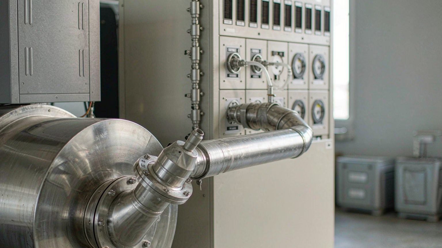
Before the analysers see gas, the sample passes through a filter, a refrigerated cold trap and a pump. Each of those stages can fail in a way that corrupts the measurement without triggering an alarm.
Particulate filters load with soot, restricting flow and slowing the sample’s transit to the analyser. Aged or discoloured tubing releases volatiles and can hold moisture. A cold trap that has lost refrigerant lets water through, and water in a CO₂ cell corrupts the reading directly; water in the pump head accelerates wear. A weak pump diaphragm produces the most confusing symptom of all — a sample that arrives late and diluted, giving a curve that looks like a slow-burning product rather than a sick instrument.
Analyser Drift
Oxygen and carbon dioxide analysers must hold drift within 0.02%. Drift accumulates over 20 minutes and shows up as a sloping baseline, which then propagates into every derived quantity. Two mundane causes dominate: ambient temperature swings in the laboratory, and insufficient warm-up time before calibration. An analyser calibrated cold and run warm will drift in a predictable direction, which is exactly why a drift that always leans the same way points at the analyser’s thermal environment rather than at the chemistry.
Burner Gas Flow Instability
The burner must deliver 30.7 ± 2.0 kW. The propane mass flow controller needs a range of at least 0–2.3 g/s and an accuracy of ±1% between 0.6 and 2.3 g/s, with propane purity of at least 95%. Manual valve systems cannot hold steady mass flow as ambient temperature changes over a long test cycle, which is why the specification calls for proper mass flow control rather than a needle valve and a pressure gauge.
The Two Calibrations That Carry the Weight
Step (Ladder) Calibration
The step calibration runs the burner through a series of defined heat output levels and compares what the apparatus measures against what the burner delivered. The acceptance criterion is that the ratio Qgas 30s(t) / HRR30s(t) stays continuously within 100 ± 5%.
Two details make this the honest test. “Continuously” is the operative word — a calibration that is correct at the low step and correct at the high step but wanders in between has a dynamic response problem that a two-point check will never reveal. And the related timing requirements are equally binding: the O₂/CO₂ analyser delay must not exceed 30 seconds, its response time must not exceed 12 seconds, the burner switching response must fall between 9 and 12 seconds, and the temperature response must not exceed 6 seconds.
n-Heptane Calibration
The n-heptane calibration burns a liquid fuel of known calorific value in the apparatus and checks the total heat release per unit mass against the target of 4,456 ± 222.8 MJ/kg. Where the step calibration isolates the burner-to-analyser agreement, the heptane test exercises everything at once: burner, duct flow, photometer, gas train, sampling timing and the calculation itself.
This is why a laboratory that cannot produce a recent heptane result is telling you something. The test is slow, it consumes a reference fuel, and it is the single most informative check available.
EN 13823 Calibration Criteria at a Glance
| Check | Criterion | What a failure looks like |
|---|---|---|
| Step calibration | Qgas 30s(t) / HRR30s(t) continuously within 100 ± 5% | Ratio correct at the ends, wandering in the middle |
| n-Heptane calibration | THR/m = 4,456 ± 222.8 MJ/kg | Consistent bias in one direction, repeated across runs |
| O₂ / CO₂ analyser response | ≤ 12 s | Peaks rounded off; FIGRA reads low |
| Analyser delay | ≤ 30 s | Time axis shifted; FIGRA distorted because it divides by elapsed time |
| Analyser drift | ≤ 0.02% | Sloping baseline; drift always leans the same way |
| Burner heat output | 30.7 ± 2.0 kW | All heat release values offset by a constant factor |
| Burner switching response | 9–12 s | Ill-defined transition between baseline and exposure |
| Propane mass flow control | Range ≥ 0–2.3 g/s, accuracy ±1% between 0.6 and 2.3 g/s | Output sags as the duct warms during a long run |
| Propane purity | Commercial propane, ≥ 95% | Energy delivered per unit mass differs from the assumption |
| Exhaust volume flow | 0.50–0.65 m³/s at 298 K | Drift that mimics material variability |
| Differential pressure sensor | Range ≥ 0–100 Pa, accuracy ±2 Pa, 90% response ≤ 1 s | Flow calculation wrong at the root |
| Duct thermocouples | 3 × K type, 0.5 mm diameter, temperature response ≤ 6 s | Temperature term in the flow and energy equations skewed |
EN 13823 Calibration Troubleshooting: Gas Path First
The single most common mistake in EN 13823 calibration troubleshooting is reaching for the analyser first. Zero and span adjustments are the easiest controls to reach and the least likely to be the cause.
Why Calibrating Before the Flow Is Restored Fails
An EN 13823 calibration is only meaningful when the sample reaching the analyser is clean, stable and sufficient. If the gas path is restricted, leaking, wet or slow, a zero and span adjustment can still succeed on a static check while the dynamic response remains wrong. The instrument then passes calibration and fails on real tests — and the operator, having just “fixed” the analyser, looks somewhere else entirely.
The correct order is: restore the gas path, confirm flow, confirm no leakage, confirm response time, and only then perform zero and span calibration. Following that order is not pedantry; it prevents a gas path fault from being silently compensated as an analyser offset.
Leak and Restriction Checks
A sample pump draws through a negative-pressure section upstream of itself. Any loose fitting, cracked tube, filter housing O-ring or condenser seal in that section admits ambient air. The symptoms are dilution and flattening: CO₂ peaks read low, CO peaks read low, oxygen depression is smaller than it should be, and the calculated heat release comes out low. Repeatability degrades while calibration still passes.
Leakage does not always show up as low flow, which is what makes it dangerous. A pump drawing air can still register a normal-looking flow while measuring the wrong gas. Practical checks: block the sampling inlet and confirm the flow falls to zero; test positive-pressure joints with soap solution; bring smoke or an alcohol swab near negative-pressure joints and watch for a reading change; inspect tubing for hardening or discolouration; check quick fittings, filter housing seals and drain bottle seals.
What the 2020+A1:2022 Edition Changed
Amendment A1 was issued in July 2022 and updated calibration procedures and precision data, so calibration documentation written against the older text may no longer match. Three changes bear directly on calibration work.
The duct flow probe changed from bi-directional to hemispherical, and the Reynolds correction coefficient Kp moved from 1.08 to 1.24. A laboratory verifying flow against a reference must use the coefficient matching its own hardware, and a laboratory that upgraded one part but not the other will see a systematic flow error.
A CO₂ correction was introduced into the heat release calculation, using a general energy value of 17.2 MJ per cubic metre of oxygen consumed. And the smoke production rate baseline window moved from 390–450 s to 210–270 s, which changes the reference level against which SMOGRA and TSP600s are computed — and therefore what a “good” photometer baseline looks like during setup.
In the current consolidated edition, calibration procedures sit in Annex C (normative) and Annex D (informative), with the calculation procedures in Annex A and precision data in Annex B. Calibration records belong to the annex that produced them, which matters when an accreditation auditor asks which procedure you followed.
When to Repeat an EN 13823 Calibration
Beyond the schedule a laboratory sets for itself, four triggers should force an EN 13823 calibration regardless of the calendar.
- After hardware replacement. A new probe, analyser, thermocouple or mass flow controller invalidates the previous calibration on the grounds that the corrected component is no longer in the chain.
- After any leak repair. Sealing a leak changes the sample path, so the dynamic behaviour must be re-established.
- When repeat tests drift in one direction. Consistent bias across nominally identical specimens points at the instrument, not the material.
- When a standard edition changes. Calibration procedures were among the elements updated by Amendment A1.
Design Choices That Reduce Drift
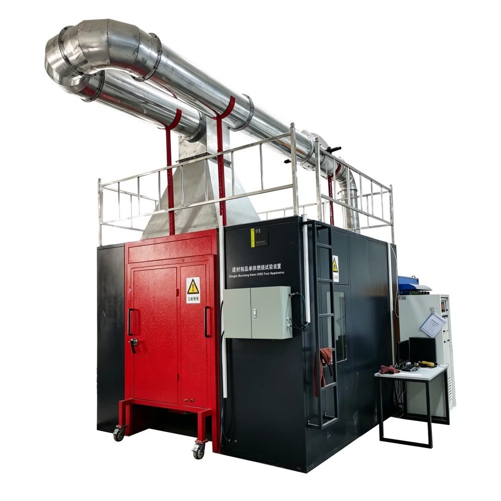
Some drift is designed in or out at purchase. Three choices matter more than the rest.
Mass flow control instead of manual valving addresses the burner output requirement directly: steady mass flow holds as ambient temperature shifts. Refrigerated cold trap capacity determines how long a laboratory can run before moisture reaches the analysers, which is why trap performance — not just the presence of a trap — belongs in the specification. And filter staging determines how quickly the sampling line loads up; a single fine filter downstream of the pump will clog quickly, whereas staged filtration protects the analysers and keeps maintenance intervals predictable.
The practical parameter set these choices map onto is listed on our fire test parameters page, and the hardware itself is described on the single burning item SBI test apparatus page.
Frequently Asked Questions
What is checked during EN 13823 calibration?
Two procedures carry the weight: the step or ladder calibration, which verifies that measured heat release tracks the burner’s known gas output continuously within 100 ± 5%, and the n-heptane calibration, which checks the whole chain against a fuel of known calorific value with a target of 4,456 ± 222.8 MJ/kg. Supporting checks cover exhaust flow, differential pressure, duct temperature, mass flow control and propane purity.
Why does my SBI test pass calibration but produce odd curves?
Because a static calibration can succeed while dynamic response is wrong. If the gas path is restricted, leaking, wet or slow, zero and span adjustment may still pass while the analyser responds late and diluted. Check flow and leakage before touching the analyser — that order prevents a gas path fault from being compensated as an analyser offset.
How often should EN 13823 calibration be repeated?
The standard sets criteria rather than a fixed calendar, so the interval depends on laboratory practice and accreditation requirements. Beyond the routine schedule, recalibrate after replacing any component in the measurement chain, after repairing a leak, whenever repeat results drift consistently in one direction, and whenever the applicable standard edition changes.
What causes oxygen analyser drift in EN 13823 testing?
Ambient temperature variation and insufficient warm-up are the most common causes, followed by moisture reaching the cell. Drift must stay within 0.02%, and it accumulates across a 20-minute run as a sloping baseline. When drift consistently leans the same direction, suspect the analyser’s thermal environment rather than its chemistry.
How do I know if my exhaust flow is wrong?
You usually cannot tell from the curve, which is the problem. Heat release is scaled by the mass of gas crossing the measurement section per unit time, so a wandering extraction rate rescales every value and looks like a product burning differently. Verify flow against a traceable reference and confirm it holds 0.50–0.65 m³/s at 298 K across a full record.
Can a leaking sample line be detected without equipment?
Partly. Blocking the sampling inlet and confirming the flow drops to zero is a strong check. Soap solution works on positive-pressure joints, and bringing smoke or an alcohol swab near negative-pressure joints while watching the reading will reveal an in-leak. Tubing that has hardened or discoloured, loose quick fittings and deteriorated O-rings are visible indicators worth inspecting.
Did the probe change affect EN 13823 calibration?
Yes. The 2020 edition replaced the bi-directional duct probe with a hemispherical probe and changed the Reynolds correction coefficient from 1.08 to 1.24. Flow verification must use the coefficient matching the installed hardware, so an apparatus with one part updated and the other not will show a systematic flow error even when every other check passes.
EN 13823 Calibration: A Sequence to Get It Under Control
- Confirm which edition the apparatus is built to, and therefore which calibration annex and coefficients apply.
- Verify exhaust flow against a traceable reference before anything else.
- Check the sampling line for restrictions and leaks, working from the probe backwards.
- Confirm analyser response and delay times, not just zero and span.
- Run the step calibration and read the ratio across the whole ramp, not at the endpoints.
- Run the n-heptane calibration and compare against the target band.
- Record which annex procedure was used, and retain the raw data.
If calibration keeps failing on the same criterion, the cause is often hardware rather than technique. Our team can review a calibration record against the instrument configuration — reach them through the contact page. Related reading: SBI test apparatus compliance, how EN 13823 data shapes classification, and SBI versus cone calorimeter.
References
- BSI Knowledge — Reaction to fire tests for building products: building products excluding floorings exposed to the thermal attack by a single burning item. knowledge.bsigroup.com
- NEN — NEN-EN 13823:2020+A1:2022 en, current edition, 101 pages, published 1 August 2022. nen.nl
- NSAI Standards — I.S. EN 13823:2020, superseded by I.S. EN 13823:2020+A1:2022. shop.standards.ie
- NBS — IS EN 13823:2020 (+A1:2022), Amendment 1 issued July 2022. thenbs.com
- NEN — NEN-EN 13501-1:2019 en, fire classification of construction products and building elements. nen.nl
- European Commission — CE marking for manufacturers under the Construction Products Regulation. ec.europa.eu
- RISE Research Institutes of Sweden — fire safety and reaction-to-fire research. rise.se
- BRE Group — fire testing and certification services. bre.co.uk
About This Guide
Prepared by the technical content team at Shenyang Baoruitong Automation Equipment (BRT), a manufacturer of reaction-to-fire and fire resistance test equipment. Calibration criteria, analyser performance limits, flow ranges and n-heptane targets quoted here come from EN 13823 and its annexes; the current consolidated edition is EN 13823:2020+A1:2022. Troubleshooting sequences reflect field practice and are offered as guidance — the standard, not this article, defines what counts as a valid calibration.