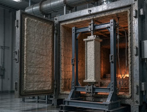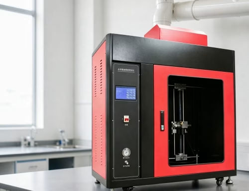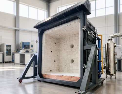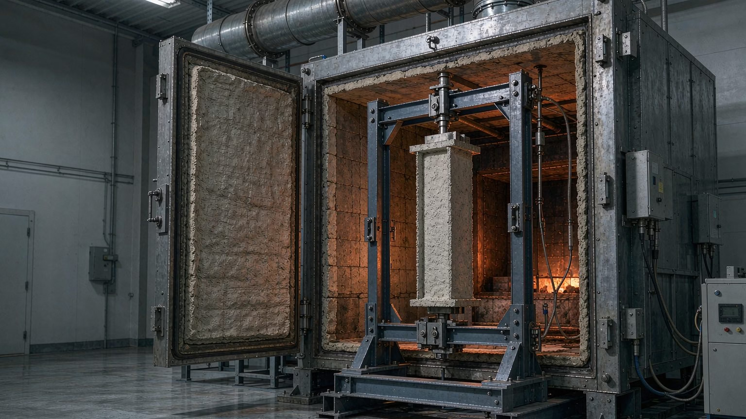
A fire resistance test measures how long a building element keeps doing its job while it is being burned. The element — a wall, floor, column, door, ceiling or cable — is mounted in a furnace, exposed to a controlled fire that follows a standard time–temperature curve, and monitored until it fails one of three criteria. The result is not a pass or fail grade but a time rating in minutes: 30, 60, 90, 120 or 240. That number then decides whether the assembly can be used in a given position in a building, and it is what a code official, an insurer and a specifier actually read.
This article explains what the test measures, how the three criteria are judged, how fire resistance differs from reaction to fire, which standards cover which elements, and why the rating carries commercial weight far beyond the lab report.
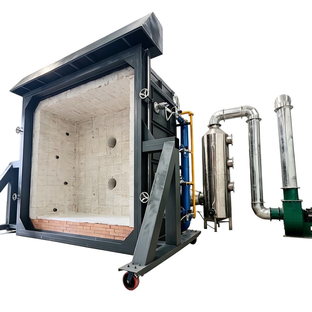
What a Fire Resistance Test Actually Measures
A fire resistance test answers one narrow engineering question: during a fire, for how long does this assembly remain a barrier and, where relevant, a load path? The furnace is not a simulation of a real fire in all its randomness. It is a deliberately standardised exposure so that results from different laboratories, different countries and different years can be compared at all 12.
The Three Performance Criteria: R, E and I
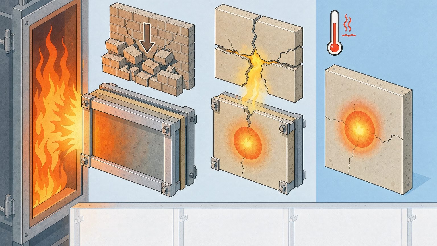
Every fire resistance rating is built from the same three criteria, and the letters travel with the rating. R (loadbearing capacity) is the ability of a loadbearing element to carry its design load without collapsing; for horizontal members the failure point is defined by limiting deflection and deflection rate, not by visible collapse [1]. E (integrity) is the ability to stop flames and hot gases passing through — judged with a cotton-wool pad test for ignition and gap gauges for sustained openings [1]. I (insulation) is the ability to keep the unexposed face below a temperature threshold, so that a person on the far side is not burned by conduction and stored heat.
The three criteria fail at different times, and the shortest one governs. A steel door may hold integrity for 90 minutes but lose insulation at 45; the published rating would then be EI 45, not E 90. This is why “the door is a 90-minute door” is almost always an incomplete statement.
The Standard Fire Curve Behind Every Test
Furnace exposure follows the standard cellulosic time–temperature curve defined in ISO 834-1 and EN 1363-1, which rises steeply and then flattens: roughly 840 °C at 30 minutes and 945 °C at 60 minutes [1][2]. Every furnace must be calibrated against that curve, and the calibration itself is a controlled activity — ISO 834-2:2019 specifies how furnace exposure uniformity is measured on simulated samples, including the type and location of instrumentation for temperature, velocity and oxygen content near the specimen surface 3.
| Curve / family | Character | Where it is used |
|---|---|---|
| Cellulosic (ISO 834, EN 1363-1, ASTM E119) | Slow, sustained growth; the classic building fire | Walls, floors, columns, doors, ceilings |
| Hydrocarbon | Faster rise, higher plateau; pool and jet fires | Tunnels, petrochemical, offshore, process plant |
| External / reduced exposure | Lower heat flux, tested with an open furnace face | Façades and elements tested for external fire spread |
The curve matters commercially because it is not interchangeable. A rating achieved on the cellulosic curve cannot be quoted against a hydrocarbon specification, and a client who needs a tunnel rating is not served by a standard building-fire report.
Fire Resistance vs Reaction to Fire: Two Different Questions
These two phrases are used interchangeably in procurement documents, and the mistake is expensive. Reaction to fire describes the material’s own contribution to a fire — how readily it ignites, how much heat it releases and how fast flame spreads across its surface. Fire resistance describes the assembly’s ability to keep separating and, where relevant, loadbearing 4.
| Question | Reaction to fire | Fire resistance |
|---|---|---|
| Subject under test | A product or material, often a small specimen | An assembly or element, full scale |
| Output | Euroclass (A1–F) or equivalent class | Time rating (e.g. R 90, EI 60) |
| Typical tests | EN ISO 1182, ISO 1716, EN 13823 SBI, EN ISO 11925-2 | ISO 834-1, EN 1363-1/2, ISO 3008, ASTM E119 |
| Read by | Product specifier, materials engineer | Structural engineer, fire consultant, code official |
Why Test Labs Report Them Separately
A wall can be non-combustible and still have poor fire resistance — a thin steel panel made of A1 material transmits heat and buckles long before a thick gypsum assembly does. Conversely, a combustible timber door leaf can achieve a strong E rating when correctly constructed. The two properties are measured on different rigs, reported in different units and consumed by different readers, so the classification system keeps them apart: reaction to fire under EN 13501-1, and fire resistance and smoke control under EN 13501-2, whose scope lists the element families — loadbearing walls, floors, beams, columns and stairs; separating walls and floors; fire doorsets, smoke control doorsets, penetration seals, service ducts and chimneys 5. For a regional survey, see our guide to global building material fire testing standards, and for the reaction-to-fire side in detail, what the four EN 13501-1 tests actually do.
The Main Fire Resistance Test Methods by Element
There is no single fire resistance test. There is a general framework, plus a family of element-specific methods that plug into it. The framework sets the furnace, the instrumentation and the acceptance logic; the element-specific method sets the specimen size, the installation details and the criteria that matter for that element [2].
Structural and Separating Elements: ISO 834-1 and EN 1363
ISO 834-1 and BS EN 1363-1 cover the broadest group: walls, floors, roofs, beams, columns, balconies, walkways and stairs. Both define the heating curve, the furnace pressure differential (vertical and horizontal elements are treated differently because pressure drives hot gas through joints), the instrument set — furnace thermocouples, unexposed-surface thermocouples, roving thermocouples, pressure and deformation sensors — and the point at which each criterion is deemed failed [1][2]. ASTM E119-22 plays the equivalent role for North American projects 6.
Doors, Shutters and Vertical Openings: ISO 3008
Door and shutter assemblies need more than a wall test, because a door also has to close, latch and cycle. ISO 3008-1:2025 is used in conjunction with ISO 834-1 and applies to hinged and pivoted doors, horizontally and vertically sliding doors including sectional doors, folding shutters, tilting doors, rolling shutter doors, removable wall panels and self-closing openable windows. Uniquely among fire tests, it includes mechanical pre-conditioning — cycling the assembly before the fire test — so the specimen is not tested in a condition it will never be in on site 7.
Cables and Circuit Integrity: IEC 60331
Not all fire resistance is about separating elements. Where a fire must not shut down a circuit — emergency lighting, fire pumps, smoke extract, alarm and evacuation systems — the property under test is circuit integrity, and the method is IEC 60331-1:2018 for cables with an overall diameter exceeding 20 mm tested with fire and mechanical shock at a temperature of at least 830 °C. The 2018 second edition extended the scope to metallic data, telecom and optical fibre cables, modified the steel test ladder, and made mass flow meters or controllers mandatory for fuel and air control 8. We explain the failure modes in detail in our article on IEC 60331 cable fire resistance testing.
| Element family | Core standard | Criteria usually reported | Example rating |
|---|---|---|---|
| Walls, floors, columns, beams | ISO 834-1 / EN 1363-1, ASTM E119 | R, E, I | REI 120 |
| Doors and shutter assemblies | ISO 3008-1:2025 (with ISO 834-1) | E, I, plus radiation where required | EI2 60 |
| Loadbearing steelwork | EN 1363-1 with EN 13381 series for protection | R | R 90 |
| Cables (circuit integrity) | IEC 60331-1:2018 / IEC 60331-2 | Continuity under fire and shock | 90 min circuit integrity |
| Through-penetration seals and joints | ASTM E814 / EN 1366 series | E, I (firestop systems) | F and T rating |
Ratings in the table are illustrative formats, not values for any specific product; the actual rating always comes from the test report for the assembly as installed.
Why Fire Resistance Testing Matters
Life Safety and Evacuation Time
A rating is a time budget. If a building’s escape strategy assumes 60 minutes of protected corridor, the separating construction has to deliver it. The 2025 edition of ISO 834-1 exists precisely so that the reported time rating is reproducible and can be relied on in that calculation [1].
Building Codes, Insurance and Project Approvals
Approval routes in most markets accept either a prescriptive rating or a tested assembly, and insurers increasingly price fire risk against evidence of tested performance. An unrated assembly is not merely non-compliant; it usually has to be replaced with a thicker, heavier or more expensive alternative that already holds a report.
Product Development and Market Access
For a manufacturer, a fire resistance report is a market-entry document. It supports product development — the design team usually learns that the weak point is the joint, not the board — and it is what allows a system to be specified, tendered and shipped. Fire protective coatings, claddings and screens all depend on it [5].
How a Fire Resistance Test Is Run, Step by Step
The sequence is deceptively simple, and most failures trace back to installation rather than materials [1][2].
| Step | What happens | What the laboratory records |
|---|---|---|
| 1. Define the field of application | The test is designed around the assembly and the variations the manufacturer needs it to cover | Specified construction and permitted variations |
| 2. Build and condition the specimen | Real joints, fixings and supporting construction are reproduced; doorsets are cycled first | Conditioning log and as-built record |
| 3. Install and instrument | Specimen mounted; unexposed-face thermocouples, deflection gauges, pressure probes and integrity devices fitted | Instrument layout and baseline readings |
| 4. Apply load and restraints | Design load applied for loadbearing elements — an unloaded specimen earns no R rating | Load magnitude and restraint condition |
| 5. Run the standard curve | Furnace follows the specified time–temperature curve to the requested duration | Temperature, pressure, deflection, integrity |
| 6. Classify and report | Test ends at failure or at the requested duration | Fire resistance duration, validity, full data set |
The reporting step carries real weight: fire resistance test reports must express validity, state the fire resistance duration, and include the measured data, with calibration status traceable to the applicable furnace exposure method [1].
Choosing Fire Resistance Test Equipment
Equipment selection follows the element, not the budget. The two questions that decide most of it are orientation — is the specimen vertical or horizontal? — and whether a load must be applied during the test.
| Equipment | Configuration | Elements it serves | Representative BRT models |
|---|---|---|---|
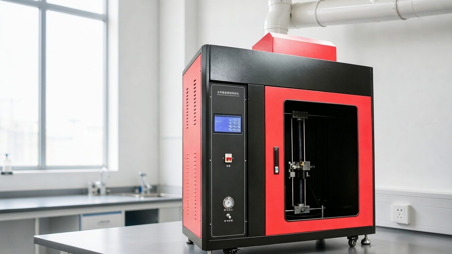
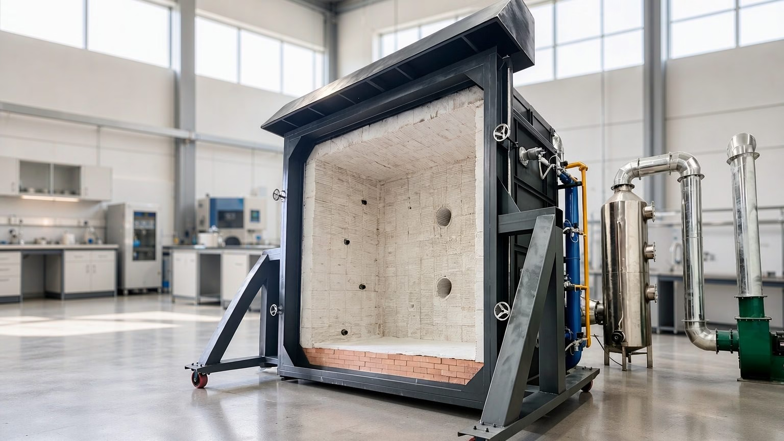
| Vertical Integrated Fire Resistance Test Furnace | Vertical furnace, multi-face exposure | Walls, partitions, columns, vertical doorsets | NH-XL |
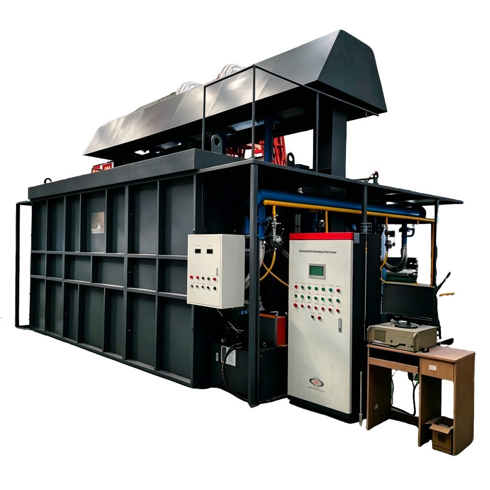
| Horizontal Fire Resistance Test Furnace | Horizontal furnace, top exposure from below | Floors, roofs, ceiling assemblies | NH-XW |
| Steel Structure Fire Retardant Coating Sample Test Furnace | Small-scale loaded furnace for coating specimens | Intumescent coating approval per EN 13381 | GTL-50 |
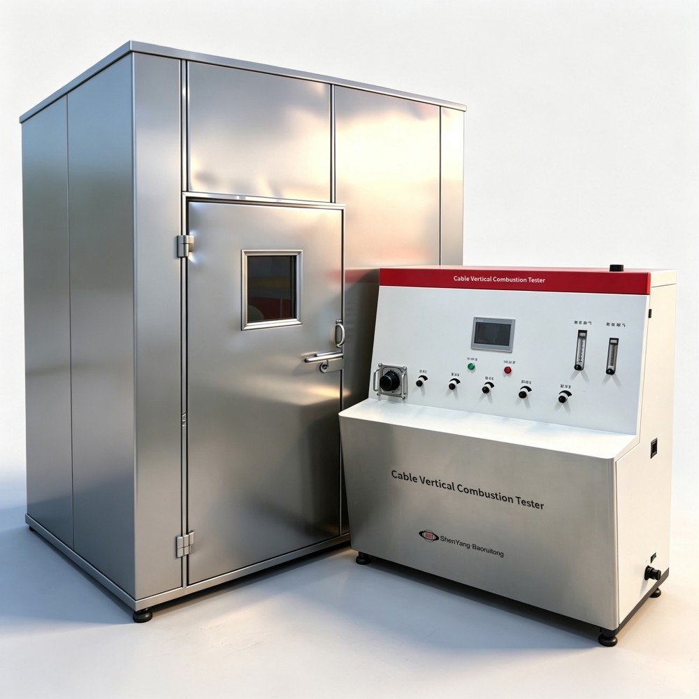
| Cable Fire Resistance Tester | Chamber with burner, shock device and continuity monitoring | Circuit-integrity cables per IEC 60331 | NH-016 |
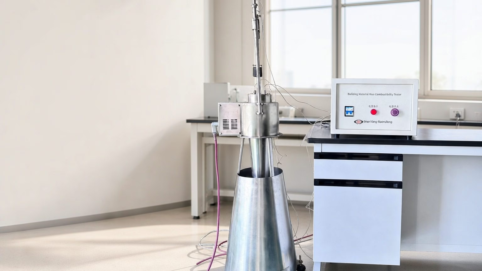
| Non-Combustibility Test Apparatus | 750 °C refractory tube furnace with centre thermocouple | Non-combustibility as a companion property | JBR20 |
| Building Materials Smoke Density Tester | Smoke chamber with photometric measurement | Smoke production alongside the FR programme | JYMD |
Furnace capability must be matched to the calibration requirement: for separating elements, exposure uniformity has to be measured and maintained to the applicable method, so furnace condition — not just maximum temperature — belongs in the specification [3]. Our full fire and flame testing equipment range covers the smoke, toxicity and heat-flux instruments that usually sit in the same laboratory, and our comparison of the SBI apparatus versus the cone calorimeter sets out where each belongs.
What Changed in ISO 834-1:2025
Version control is where a lot of tender documents quietly go wrong. ISO 834-1:2025 was published on 29 May 2025 and replaces ISO 834-1:1999 together with its Amendments 1:2012 and 2:2021 [1]. The 2025 edition consolidates the general requirements — equipment and furnace behaviour, instrumentation, standard heating curves and tolerances, furnace pressure differential, specimen preparation, procedure, performance criteria and reporting — into one current text.
That has two practical consequences. First, a report or datasheet that still cites “ISO 834-1:1999” is not automatically wrong — it is simply an older basis, and buyers should ask which edition a supplier is working to. Second, the companion documents matter as much as the headline standard: ISO 834-2:2019 governs how furnace exposure is measured and is currently under revision [3], while ISO 3008-1 moved to a 2025 edition at the same time as the general requirements [7]. Checking edition years is the cheapest due diligence available.
Frequently Asked Questions
What is a fire resistance test?
A fire resistance test measures how long a building element keeps performing its function while exposed to a controlled fire inside a test furnace. The specimen is instrumented, loaded where it is loadbearing, and heated along a standard time–temperature curve until it fails on loadbearing capacity (R), integrity (E) or insulation (I). The outcome is a time rating in minutes, which is then used to justify the element’s position in a building.
How is fire resistance measured — what do R, E and I mean?
The rating is assembled from three criteria, each with its own failure definition. R is loadbearing capacity and is judged by limiting deflection and deflection rate for horizontal elements. E is integrity, judged by whether flames or hot gases escape, tested with a cotton-wool pad and gap gauges. I is insulation, judged by the temperature rise on the unexposed face. The whole rating is limited by whichever criterion fails first.
What is the difference between fire resistance and reaction to fire?
Fire resistance describes how long an assembly keeps separating and loadbearing during a fire, and is reported as a time rating. Reaction to fire describes the material’s own contribution to fire — ignitability, heat release and flame spread — and is reported as a class such as A1 to F. They are tested on different rigs, reported in different units, and read by different people on a project.
How long does a fire resistance test take?
The fire exposure itself lasts only as long as the requested rating, so a 60-minute test is an hour of heating. The elapsed project time is far longer, because specimen construction, conditioning, instrumentation and installation typically take days, the report takes weeks, and door assemblies also require mechanical pre-conditioning by cycling before the fire test begins. Plan the test date against the tender date, not the other way round.
Which fire resistance standard applies to my product?
It depends on the element and the market. Walls, floors, columns and beams follow ISO 834-1 and EN 1363-1 in most of the world, with ASTM E119 in North America. Doors and shutters follow ISO 3008-1, or EN 1634-1 in Europe. Cables that must keep working during a fire follow IEC 60331. If your product is a coating, a penetration seal or a duct, there is a dedicated method for it, so confirm the route before building the specimen.
Can a fire resistance test be done on a full-size assembly?
Yes, and for most separating elements it must be. The specimen has to represent the real construction, including joints, fixings, supporting construction and any services passing through it, because these details usually govern the result. Small-scale furnaces are used for specific purposes such as loaded coating specimens, but they cannot stand in for a full-size wall, floor or door assembly.
Does a fire resistance rating expire?
The rating belongs to the assembly as tested, so it does not expire in the way a certificate does. What changes is the basis: standards are revised, and a report issued against a superseded edition may need re-assessment when a project specifies the current version. Manufacturers also change designs, and any deviation from the tested specification moves the assembly outside its field of application.
Next Steps: Plan Your Fire Resistance Test Programme
Decide in this order, and most of the ambiguity disappears before you spend money:
- Name the element and its position — separating or non-separating, loadbearing or not, vertical or horizontal.
- Fix the target rating and criteria — REI 60 is a different specification from E 60.
- Confirm the standard and the edition the project or market actually requires.
- Choose the exposure curve — cellulosic for general building, hydrocarbon for process and tunnel work.
- Define the field of application you need to cover, so the specimen is not built too narrowly.
- Select equipment that can hold the curve and, where separating elements are involved, support the calibration method.
If you would like a second opinion on which furnace configuration fits an element you are about to test, tell us what you are building and we will map it to the right method and apparatus. You can also review the key test parameters our fire laboratories work to before you specify.
About the author. This article was prepared by the application engineering team at Shenyang Baoruitong Automation Equipment Co., Ltd. (BRT Testing), which designs and manufactures fire and flame testing equipment, UV/Vis and FTIR spectrometers, and plastic pipe testing systems for laboratories in more than 40 countries. We build the furnaces, so we work with the standards directly — but we are not a certification body, and a rating is only valid when issued by an accredited test laboratory against the assembly as installed.
Standards are revised on their own schedule. Where an edition year is given in this article, it reflects the status verified at the time of writing; confirm the current edition before quoting a rating in a tender.