- What a Fire Resistance Test Procedure Actually Measures
- The Standard Fire That Every Fire Resistance Test Procedure Follows
- Running a Fire Resistance Test Procedure, Stage by Stage
- Instrumentation That Decides the Result of a Fire Resistance Test Procedure
- What Counts as Failure in a Fire Resistance Test Procedure
- Element by Element: Which Fire Resistance Test Procedure Applies
- Calibration, Validity and Direct Application of the Result
- What the Apparatus Has to Deliver
- Frequently Asked Questions
- What is a fire resistance test procedure?
- How is failure determined during the test?
- What is the difference between R, E and I?
- Does ISO 834-1 or EN 1363-1 apply?
- What is the role of plate thermometers?
- Can one test result cover several wall designs?
- Is a fire resistance test the same as a non-combustibility test?
- Next Steps
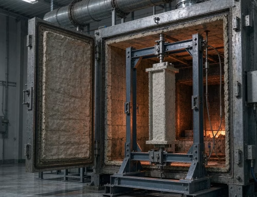
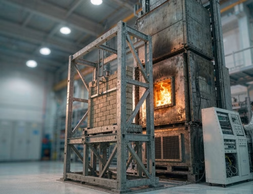
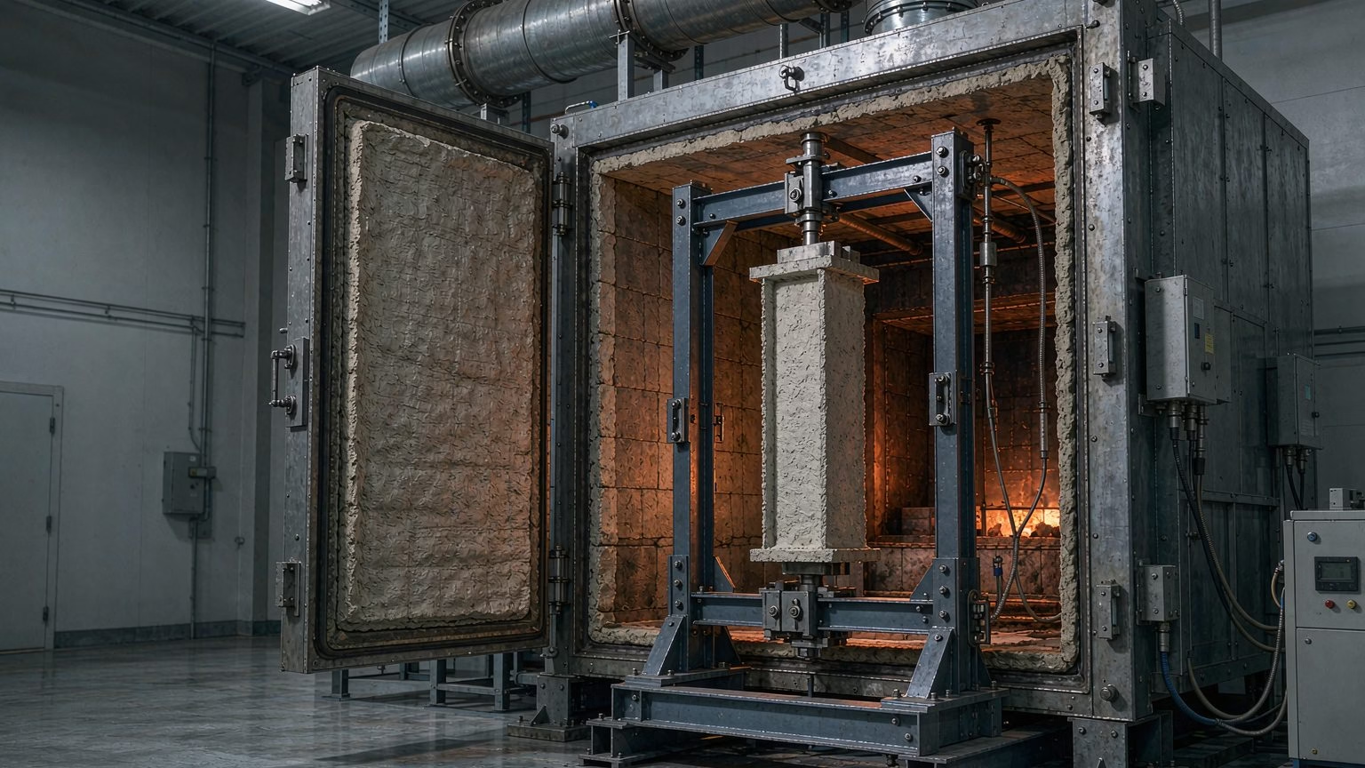
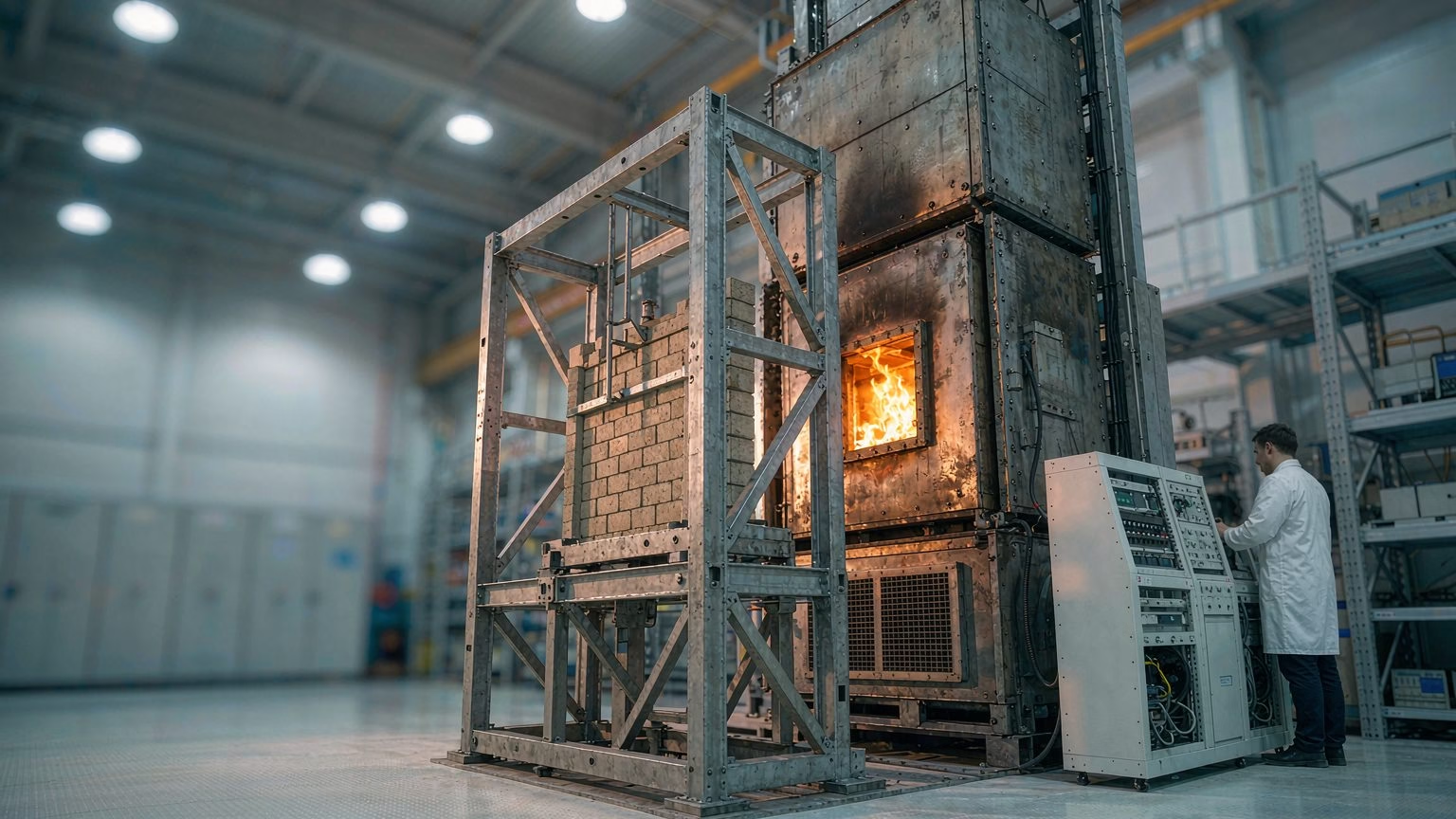
A fire resistance test procedure is a full-scale furnace test: an element of construction — wall, partition, floor, beam, column or door assembly — is built into a restraint frame, loaded if it is designed to carry load, heated along a standard time-temperature curve, and monitored until it fails one of three criteria or survives the required exposure period. Those criteria are loadbearing capacity (R), integrity (E) and insulation (I). Unlike a reaction-to-fire test, which rates how a material contributes to a fire, this procedure rates how long an assembly keeps a fire inside the compartment where it started.
What a Fire Resistance Test Procedure Actually Measures
Fire resistance is a duration, not a score: for how many minutes does this element keep satisfying the criteria? ISO 834-1 gives each criterion its own subclause — 10.2.2 for loadbearing capacity, 10.2.3 for integrity, 10.2.4 for insulation 12.
The Three Criteria: R, E and I
Loadbearing capacity (R) is the ability to keep carrying the applied load without collapsing or deforming beyond a limit. Integrity (E) is the ability to stop flames and hot gases passing through — a barrier property, not a strength property. Insulation (I) is the ability to limit the temperature rise on the unexposed face, so the safe-side surface stays below the level that would ignite stored materials. The letters identify which requirement is certified: a loadbearing wall is rated REI, a non-loadbearing partition EI, a fire door usually EI.
Why a Fire Resistance Test Procedure Is Not a Material Test
It says nothing about whether the materials in the assembly are combustible: a gypsum-lined steel stud partition rated EI 60 can contain combustible components, and an all-concrete element can still fail on integrity if a service penetration is poorly sealed. Materials are classified separately — by the non-combustibility test to ISO 1182, and by reaction to fire testing behind the Euroclass system 9. Our survey of global building material fire testing standards maps where each is mandatory.
The Standard Fire That Every Fire Resistance Test Procedure Follows
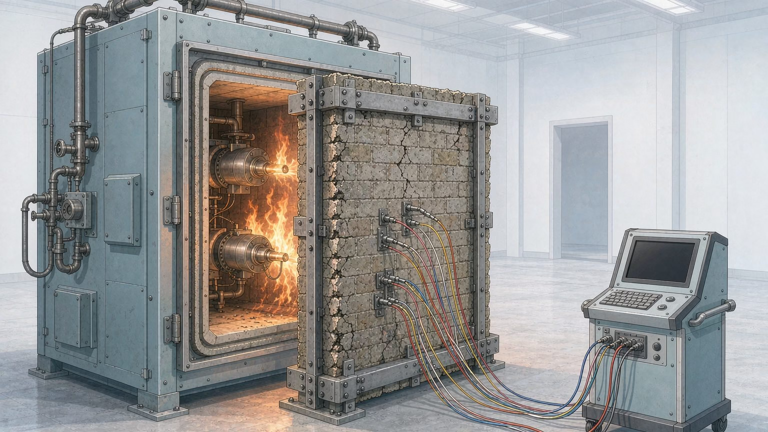
A fire resistance test procedure cannot heat the specimen however the fuel allows. It must follow a defined time-temperature relationship within a stated tolerance band throughout: ISO 834-1 specifies the curve in Clause 6.1.1 and the tolerances in Clause 6.1.2 [2]. The 2025 edition covers elements “represented with standardized time-temperature curves” — plural, because more than one curve is now normative [1][2].
| Curve | Where it comes from | Character | Typical use |
|---|---|---|---|
| Cellulosic (ISO 834 / EN 1363-1) | ISO 834-1 Clause 6.1.1; EN 1363-1 | Rises steeply, then flattens | Buildings — walls, floors, beams, columns, doors |
| Hydrocarbon | EN 1363-1, additional curve | Near-instant step to a much higher plateau | Petrochemical and offshore structures |
| External fire exposure | EN 1363-2 | Lower and less severe than the cellulosic curve | External walls exposed from outside |
| Slow heating / smouldering variants | EN 1363-1, additional curves | Deliberately reduced heating rate | Where the cellulosic curve over-states exposure |
The tolerances matter more than the formula: the furnace must track the curve inside an upper and lower envelope at every point in time, measured by the instruments the standard nominates rather than by the burner controller’s setpoint.
Why the 2025 Edition of ISO 834-1 Matters
ISO 834-1 was published in 2025 as the second edition, prepared by ISO/TC 92/SC 2, Fire Resistance [1]. Its Foreword states that it cancels and replaces ISO 834-1:1999 and ISO/TR 834-3:2012, incorporates Amd 1:2012 and Amd 2:2021, and that the content has been aligned with EN 1363-1, additional curves added and the loadbearing criteria changed [2].
That alignment matters practically. EN 1363-1 was revised in 2020 to give laboratories a fairer basis for judging specimens regardless of failure mode, and ISO/TC 92/SC 2 adopted those changes rather than keep a divergent international text 38. A report citing ISO 834-1 without a year should be read with care.
Running a Fire Resistance Test Procedure, Stage by Stage
ISO 834-1 defines the sequence below, from specimen preparation through to the test report [2].
| Stage | What happens | What the laboratory records |
|---|---|---|
| Specimen design and construction | The element is built exactly as it will be built on site, including joints, fixings and penetrations | Materials, dimensions, build method, moisture content |
| Installation in the frame | The specimen is mounted with the specified boundary conditions | Restraint conditions, gaps, seal details |
| Conditioning | The specimen is cured or dried to the condition the standard requires | Conditioning period and ambient conditions |
| Instrumentation | Plate thermometers, unexposed-face thermocouples, a roving thermocouple, pressure probes, deformation transducers and load cells are fitted | Every instrument position, and its calibration status |
| Load and restraint application | The design load is applied and held before ignition | Load value, load distribution, restraint forces |
| Heating | The furnace follows the control curve; temperature, pressure and deformation are logged continuously | The full time series, not just the peak values |
| Integrity monitoring | Cotton pad and gap gauges are applied wherever hot gas is suspected to be escaping | Time and location of each check and its outcome |
| Termination | The test stops when a criterion fails, or at the end of the requested period | The criterion that ended the test, and the elapsed time |
| Assessment and report | The data are reduced and the result expressed as a rating | The reported classification and its field of application |
Two habits separate a usable result from a useless one. The load must be applied and stable before the furnace is lit, because a load introduced during heating changes the failure mode. And temperature and pressure records must be continuous, because Clause 11 on validity is judged against the whole record, not the reading at the moment of failure [2].
Instrumentation That Decides the Result of a Fire Resistance Test Procedure
Because the criteria are measured, the instruments are effectively part of the specification: a furnace that reaches the right temperature but measures it in the wrong place produces a result that cannot be defended.
Furnace Temperature: Plate Thermometers, Not Bare Thermocouples
Clause 5.5.1 covers temperature instrumentation and Clause 8.1.1 nominates plate thermometers for measuring furnace exposure [2]. A plate thermometer has a shielded, insulated sensing junction, so it responds to the combined radiative and convective heat flux the specimen sees rather than to gas temperature alone. Using bare thermocouples where plate thermometers are specified is a common reason a furnace passes its own checks but fails a third-party assessment.
Unexposed Face: Fixed and Roving Thermocouples
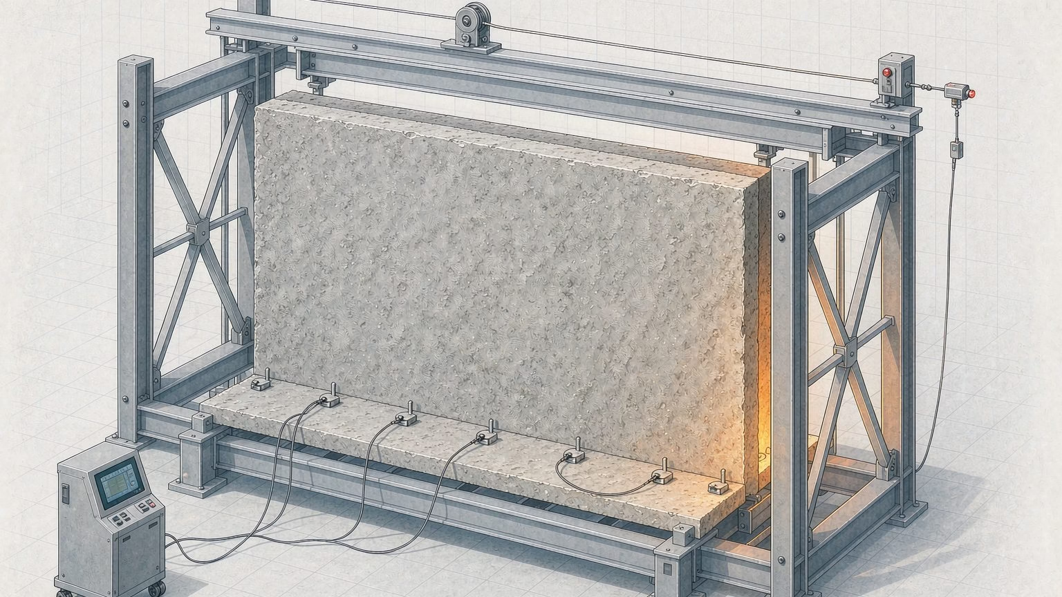
The insulation criterion is judged on the face not exposed to the fire. Clause 8.1.2 covers the fixed unexposed-surface thermocouples and Clause 8.1.3 the roving thermocouple [2]. The fixed array gives the average temperature rise; the roving thermocouple searches for the single hottest point, which is why a report should name which instrument produced the peak reading.
Pressure, Load and Deformation
Furnace pressure is controlled because it drives hot gas through every joint in the specimen, and load and deformation supply the two numbers that define failure of a loadbearing element.
| Measured quantity | Where the requirement sits | Why it decides the result |
|---|---|---|
| Furnace pressure differential | Clause 6.2, separately for vertical and horizontal elements; measurement in Clause 8.2 | Drives hot gas through joints, so it changes both integrity and insulation outcomes |
| Applied load | Clause 5.5.3 | Defines the loadbearing capacity (R) failure thresholds |
| Deflection, expansion and contraction | Clause 5.5.4 | Limiting deflection, rate of deflection and contraction values end the test |
Both load and deformation must be logged continuously rather than sampled [2].
Integrity Devices: Cotton Pad and Gap Gauges
Integrity is checked with physical devices, not instruments. Clause 8.4.1 specifies a cotton wool pad and Clause 8.4.2 gap gauges [2]. A pad is held near the unexposed face wherever a leak is suspected, but not above roughly 300 °C, because above that it can char from radiant heat alone and give a false failure. The gap gauges are the objective half of the check: a 6 mm gauge that passes through a crack and slides 150 mm, or a 25 mm gauge that passes fully through, shows an integrity failure without a judgement about smoke 10.
| Instrument | What it measures | Which criterion it feeds |
|---|---|---|
| Plate thermometers in the furnace | Furnace exposure as heat flux | Furnace control and test validity |
| Fixed unexposed-face thermocouples | Average temperature rise on the cold face | Insulation (I), average limit |
| Roving thermocouple | Hotspot temperature on the cold face | Insulation (I), single-point limit |
| Pressure probe | Furnace pressure differential at the nominated height | Test validity and comparability |
| Load cell | Applied load throughout the exposure | Loadbearing capacity (R) |
| Deflection and axial deformation transducers | Deflection, expansion or contraction | Loadbearing capacity (R) limits and rates |
| Cotton wool pad | Ignition of combustible material by escaping hot gas | Integrity (E) |
| Gap gauges, 6 mm and 25 mm | Physical passage of hot gas through a crack | Integrity (E) |
What Counts as Failure in a Fire Resistance Test Procedure
Failure is defined, not observed. A test ends when a threshold in Clause 10.2 is crossed, and the reported fire resistance is the elapsed time at that moment. The thresholds are temperature rises, so the unit is the kelvin, and 1 K equals 1 °C of rise [10].
Loadbearing Capacity (R)
Clause 10.2.2 applies to loaded elements [2]. Failure is recorded when the specimen collapses, or when deformation exceeds two limits — a limiting deflection and a limiting rate of deflection. Both are expressed in terms of span and element depth, so permitted movement scales with the member rather than being a fixed distance. Vertical elements are judged on contraction as well, with separate limits for total contraction and for its rate. The changes made to these criteria in the 2025 edition are why the year should be quoted [2].
Integrity (E)
Clause 10.2.3 covers integrity [2]. Any one of the following ends the test: ignition of the cotton wool pad; passage of the 6 mm gap gauge through a crack combined with 150 mm of sliding along it; full passage of the 25 mm gap gauge; or sustained flaming on the unexposed face lasting more than about ten seconds [10]. This criterion most often fixes a door rating, because a gap at the closing edge shows up as a leak long before the assembly loses structural coherence.
Insulation (I)
Clause 10.2.4 covers insulation [2]. The element fails when the average temperature rise on the unexposed face exceeds 140 K above its initial average, or the rise at any single point exceeds 180 K above that point’s initial temperature [10]. A specimen that starts cold therefore has more margin than one conditioned warm. The single-point limit catches thermal bridges: a steel fixing, aluminium frame or metal duct conducting heat through the assembly creates a local hotspot that can fail an otherwise sound construction.
How the Criteria Cascade
The criteria are not independent; Clause 12.2 says so. If loadbearing capacity fails, integrity and insulation are automatically treated as failed; if integrity fails, insulation is automatically treated as failed [2]. A manufacturer holding a 60-minute loadbearing result with a 47-minute integrity result therefore does not hold an R 60 rating and cannot report one.
| Criterion | Symbol | What is measured | Failure threshold |
|---|---|---|---|
| Loadbearing capacity | R | Collapse, deflection and rate of deflection; contraction and rate of contraction for vertical elements | Beyond the limiting values, or collapse |
| Integrity | E | Cotton pad ignition; 6 mm gap gauge plus 150 mm of sliding; full passage of 25 mm gap gauge; sustained flame on unexposed face | Any one of these occurs |
| Insulation | I | Temperature rise on the unexposed face, average and at any single point | Mean rise over 140 K, or any point rise over 180 K |
Element by Element: Which Fire Resistance Test Procedure Applies
The general requirements do not test anything on their own: each element type has a specific procedure that inherits the curve and criteria and adds the geometry, loading and boundary conditions it needs.
| Element | Standard carrying the specific requirements | Criteria that apply |
|---|---|---|
| Non-loadbearing walls and partitions | EN 1364-1, used with EN 1363-1 4 | EI |
| Loadbearing walls | EN 1365-1, used with EN 1363-1 5 | REI |
| Floors, roofs, beams and columns | EN 1365-2 to EN 1365-4 | R or REI, depending on member |
| Doors, shutters and openable windows | EN 1634-1 | EI or E, per the declared class |
| Fire protection systems applied to steel | EN 13381 series | The contribution to the steel member’s R |
| Service installations: ducts, dampers, cables | EN 1366 series | E, EI or the declared performance |
| General international basis | ISO 834-1, with parts for specific elements [1] | R, E, I as applicable |
| North American basis | ASTM E119 6 | Structural and thermal criteria in the same sense |
| UK legacy basis | BS 476 Parts 20 to 24 | Element-dependent |
EN 1364-1 is explicit about its boundaries, and they are frequently misread: it applies to non-loadbearing partitions with and without glazing and to glazed non-loadbearing walls, but not to curtain walls unless permitted under EN 1364-3/4, nor to walls containing door assemblies, which are tested to EN 1634-1 [4].
The North American route follows the same logic with different vocabulary. ASTM E119 covers assemblies of masonry units and of structural materials — walls, partitions, columns, beams, slabs, and floor and roof assemblies — and evaluates for how long an element contains a fire, retains its structural integrity, or both. It is equally explicit about what it does not provide: untested components or lengths, smoke or toxic gas contribution, smoke passage control, joints between elements, or surface flame spread [6].
Calibration, Validity and Direct Application of the Result
A fire resistance test procedure only produces a rating if the test was valid. Clause 6.6 covers deviation from the specified test conditions and Clause 11 governs validity as a whole [2]. A certification body asks whether the furnace tracked the curve, and the pressure, inside the required envelope for the whole exposure; a sustained excursion is normally excluded. ISO 834-2 sets requirements for measuring furnace exposure on test samples 7.
There is also a limit on how far a single result travels: EN 1364-1 and EN 1365-1 both close with a clause on the field of direct application of test results [4][5]. A tested assembly can be applied to other similar constructions only within that field; anything outside it needs an extended application assessment by a recognised body.
What the Apparatus Has to Deliver
A fire resistance furnace is a controlled environment, and the controls that matter are the ones the standard names: curve following within tolerance, plate-thermometer-based temperature measurement, closed-loop pressure control, and continuous load and deformation logging.
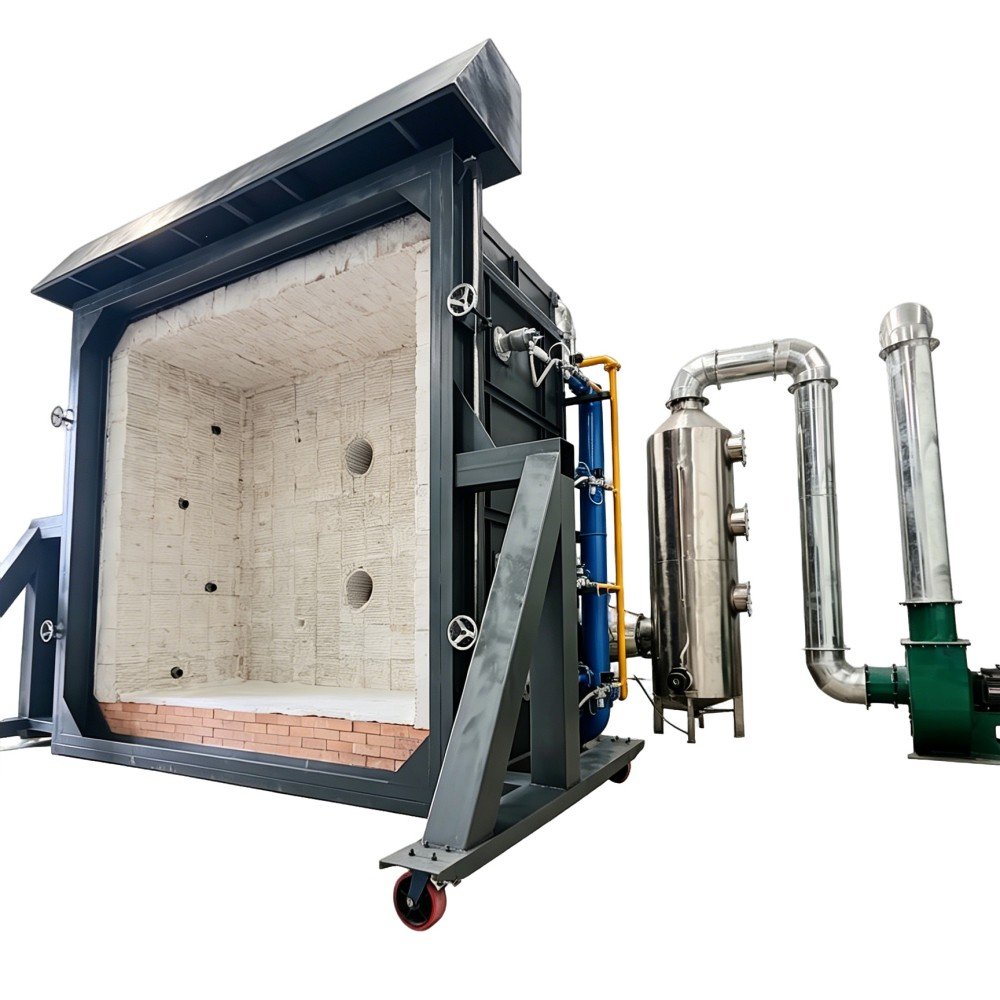
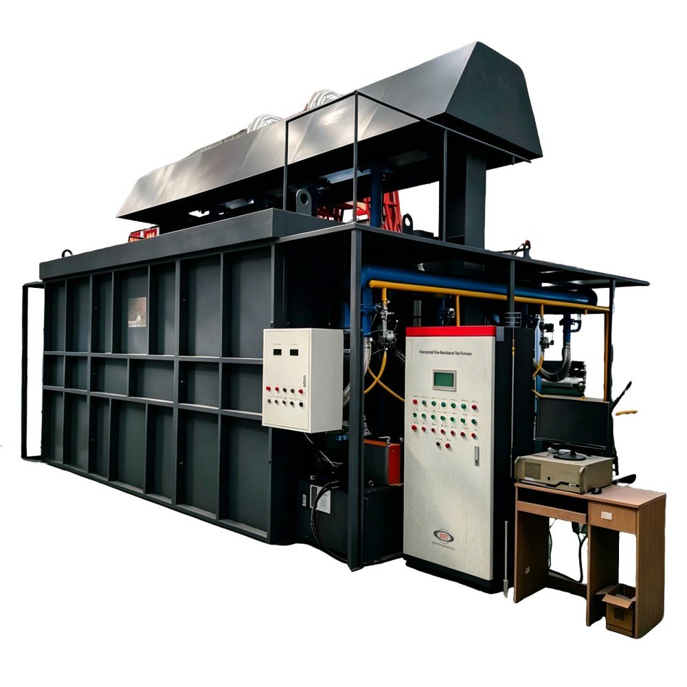
Our NH-XL vertical integrated fire resistance test furnace covers vertical separating elements — fire doors, windows, shutters, glazing and partition walls — in a 3.0 m cavity lined with high-alumina zirconia fibre rated to 1300 °C, with eight proportional gas burners and closed-loop pressure control. Its horizontal counterpart, the NH-XW horizontal fire resistance test furnace, covers floor slabs, concrete and steel beams, decks and intumescent coatings.
| Apparatus | Element it tests | Standards named by the manufacturer |
|---|---|---|
| NH-XL vertical integrated fire resistance test furnace | Fire doors, windows, shutters, glazing, partition walls | ISO 834-1/4/8, EN 1363-1, EN 1634-1, BS 476 Parts 20/22, ASTM E119, UL 263, GB/T 9978, GB 12955, GB 16809 |
| NH-XW horizontal fire resistance test furnace | Floor slabs, beams, concrete decks, intumescent coatings | ISO 834-1/5/6, EN 1363, EN 1365, BS 476, ASTM E119, ASTM E1529, UL 263, UL 1709, AS 1530.4, GB/T 9978, GB 14907 |
| GTL-50 steel structure fire retardant coating test furnace | Steel plates and members with fire-retardant coatings | ISO 834, BS 476 Parts 20/21, EN 13381-4/8, ASTM E119, UL 263, GB 14907 |
| NH-016 cable fire resistance tester | Power, data and optical cables under circuit-integrity test | IEC 60331 series, BS 6387, BS 8491, BS 8436, EN 50200, GB/T 19216 |
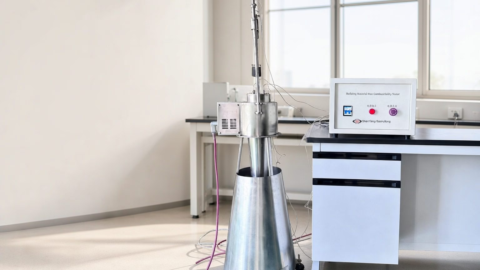
| JBR20 non-combustibility test apparatus | Homogeneous building products and substantial components | ISO 1182, EN ISO 1182, ASTM E136, BS 476-4, GB/T 5464, EN 13501-1 A1/A2 |
| JCDT single burning item test apparatus | Building products other than floorings | EN 13823, EN 13501-1, GB/T 20284 |
Reaction-to-fire testing runs on the single burning item apparatus to EN 13823, whose calibration we cover in the EN 13823 SBI calibration guide. Cable circuit integrity is described in our article on the IEC 60331 cable fire resistance test.
Frequently Asked Questions
What is a fire resistance test procedure?
It is a full-scale furnace test: an element of construction is built into a frame, loaded if loadbearing, heated along a standard time-temperature curve, and monitored until it fails one of three criteria or survives the required period. The result is a time in minutes, which becomes the element’s fire resistance rating.
How is failure determined during the test?
Against defined thresholds, not by observation. Insulation fails when the mean temperature rise on the unexposed face exceeds 140 K, or at any single point exceeds 180 K. Integrity fails on cotton pad ignition, on the 6 mm gap gauge sliding 150 mm along a crack, on the 25 mm gauge passing through, or on a flame on the unexposed face sustained beyond about ten seconds. Loadbearing capacity fails on collapse or on deformation past the limiting deflection, rate or contraction values.
What is the difference between R, E and I?
R is loadbearing capacity, the ability to keep carrying load without collapsing or deforming past a limit. E is integrity, the ability to stop flames and hot gases passing through. I is insulation, the ability to limit the temperature rise on the unexposed face. They are not interchangeable: a non-loadbearing partition is EI, a loadbearing wall REI, a fire door usually EI.
Does ISO 834-1 or EN 1363-1 apply?
Both can. ISO 834-1:2025 states that its content has been aligned with EN 1363-1, that additional curves were added and that the loadbearing criteria changed; EN 1363-1 was revised in 2020. A European project usually runs EN 1363-1 with the relevant EN 1364, EN 1365, EN 1634 or EN 13381 part; a wider international project runs ISO 834-1 or ASTM E119.
What is the role of plate thermometers?
They measure furnace exposure because their shielded, insulated junctions respond to the combined radiative and convective heat flux the specimen experiences, not to gas temperature alone. Using bare thermocouples where plate thermometers are specified is a common reason a furnace fails a third-party assessment.
Can one test result cover several wall designs?
Only within limits. EN 1364-1 and EN 1365-1 both close with a clause on the field of direct application of test results, which restricts how far a tested assembly can be varied without further evidence. Changes outside that field need an extended application assessment by a recognised body.
Is a fire resistance test the same as a non-combustibility test?
No. A non-combustibility test such as ISO 1182 or ASTM E136 assesses whether a material itself contributes fuel, using small specimens in a 750 °C vertical tube furnace. A fire resistance test assesses a complete element and rates how long it holds its separating or loadbearing function.
Next Steps
If you are commissioning a fire resistance test procedure, settle these six points in order:
- Name the element and the market. The element type fixes the standard and the criteria letters.
- Quote the year of the edition. ISO 834-1 was reissued in 2025 with the loadbearing criteria changed.
- Decide the criteria you need: REI, EI or E, and the period the rating will carry.
- Fix the specimen build before the frame, because the field of direct application constrains later variation.
- Check the instrumentation: plate thermometers, fixed and roving unexposed-face thermocouples, pressure, and continuous load and deformation logging.
- Confirm the furnace holds the curve and pressure envelope for the whole period.
If you would like help matching an element and a target rating to the right furnace, tell us what you are testing and we will work through the criteria with you. The full fire and flame testing equipment range lists configurations side by side.
About the author. Prepared by the application engineering team at Shenyang Baoruitong Automation Equipment Co., Ltd. (BRT Testing), which manufactures fire resistance furnaces, combustion testers and analytical instruments. We build the apparatus that runs these methods, so we work with the criteria directly — but we are not a certification body.
Standard editions are revised on their own schedule. Confirm the current editions before quoting a rating.