The Short Answer
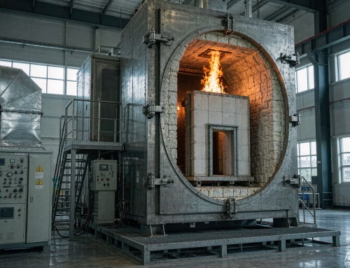
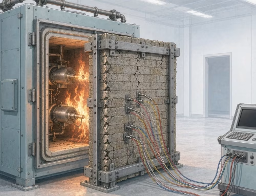
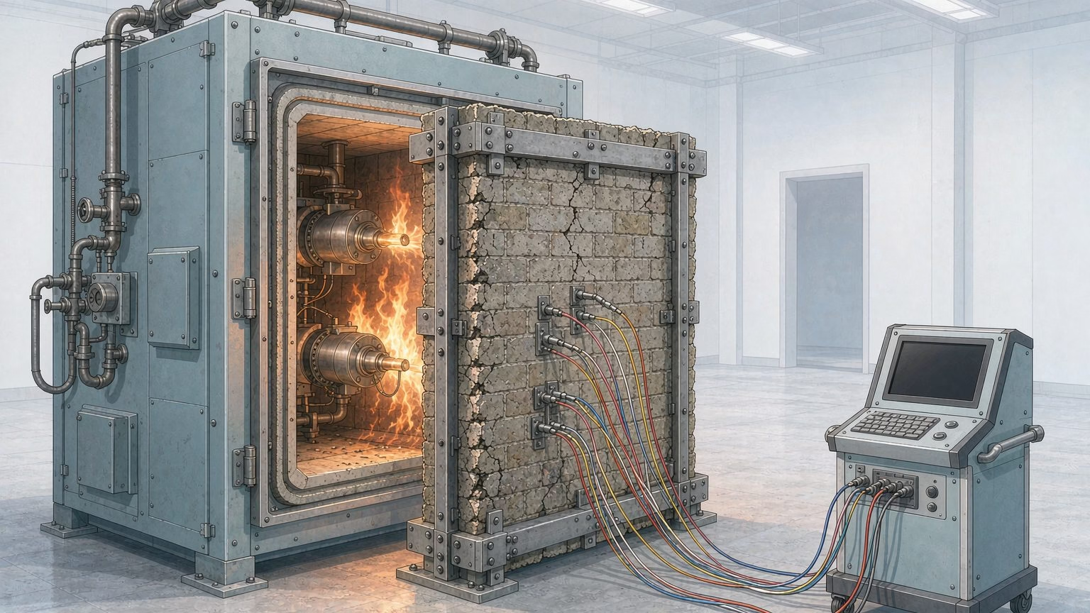
A fire resistance test furnace is a calibrated exposure machine, not an oven. Its job is to impose one agreed time-temperature fire on a full-size building element and to hold that exposure within a tolerance tight enough that a result obtained in one laboratory means the same thing in another. A chamber lined with refractory material, a burner train, an instrument set and a loading frame do the work between them. It is worth separating this from the reaction to fire family of tests at the outset: a furnace asks how long an assembly keeps performing, while reaction-to-fire methods ask how much a material feeds a growing fire. The same split shows up in the difference between fire resistance and flame retardancy, which is worth reading first if the two are currently being used interchangeably in your specifications. The chamber defines the exposed face, the burners track the curve, plate thermometers measure the thermal dose the specimen actually receives, pressure probes hold the furnace at the specified differential, and the instrument set on the unexposed face records when the element stops performing. What comes out is not a single pass or fail but three independent criteria — R for load-bearing capacity, E for integrity and I for insulation — each with its own failure point and its own time in minutes 13. The edition of the governing standard matters too: ISO 834-1 was republished in 2025, and the first edition from 1999 together with its two amendments and its commentary document were all withdrawn on the same day [1]2.

What a Fire Resistance Test Furnace Must Reproduce
The standard time-temperature curve
The reference exposure for most building elements is the ISO 834 cellulosic curve, defined by the equation T = 20 + 345 log₁₀(8t + 1), where T is the furnace temperature in degrees Celsius and t is the time in minutes. The values that matter in practice are the ones a specifier will quote back: approximately 842 °C at 30 minutes, 945 °C at 60 minutes, 1006 °C at 90 minutes and 1049 °C at 120 minutes. We cover the curve itself — its tolerances, how furnace control is judged against it, and how the hydrocarbon and tunnel variants differ — in a separate article on ISO 834 fire resistance testing. Those four numbers are the reason a fire resistance furnace has to be built differently from a heat-treatment furnace — the demand is not a setpoint but a trajectory, and the burner system has to keep climbing for two hours or more.
Why the curve alone is not the exposure
Two furnaces can both follow the same curve and still deliver different fires, because the gas temperature is only part of what the specimen receives. Radiation from the hot lining, flame impingement from the burners and the velocity of the gas across the surface all contribute, and all three depend on furnace geometry, burner number and position, and the fuel used. That sensitivity is exactly why the measuring device inside the furnace was changed 5. A bare-wire thermocouple sits in dynamic equilibrium with a gas whose convective component dominates for a small body, while a large specimen is heated mainly by radiation. The plate thermometer was adopted instead, on the reasoning that a device which receives the same thermal dose as the specimen removes the furnace geometry from the result [5].
How a Fire Resistance Test Furnace Is Built
Chamber, lining and opening
Start with the chamber. In a fire resistance test furnace the chamber is a steel shell lined with refractory material, and the lining is specified rather than left to the builder: density below 1000 kg/m³, minimum thickness 50 mm, covering at least 70 % of the internal surface, so that the walls store and re-radiate heat rather than acting as a heat sink [5]. The opening is the practical constraint on everything else, because a fire resistance test is normally run on a full-size element. Decide the largest wall, floor or door assembly you will ever need to test and size the opening to that, not to the job in front of you.
Burners, fuel and control
Burner count, placement and fuel are the variables the standard deliberately does not fully fix, which is why furnace control is judged on the thermal dose rather than on the hardware. Natural gas and liquefied petroleum gas are both used; what matters is that the control system can drive the measured curve and hold it there for the full duration, and that the fuel supply is stable enough that a pressure dip part-way through a two-hour run does not become an excursion.
Measuring furnace temperature: plate thermometers
| Subsystem | What it does | What constrains it |
|---|---|---|
| Chamber and lining | Defines the exposed face and supplies most of the radiant heat | Lining density < 1000 kg/m³, ≥ 50 mm thick, ≥ 70 % of internal surface [5] |
| Burner train | Tracks the time-temperature curve for the full test duration | Burner layout and fuel are not fully standardised; the thermal dose is what is controlled |
| Furnace thermometry | Measures the thermal dose received by the specimen | Plate thermometer: 150 mm × 100 mm × 0.7 mm nickel-alloy folded plate, K-type thermocouple at the centre, insulating pad behind [5] |
| Pressure instrumentation | Holds the specified furnace pressure differential | T-shaped or tubular probes; ± 2 Pa accuracy [5] |
| Loading and restraint | Applies the service load and reproduces boundary conditions | Load must be applied and held for the duration; the frame must simulate real restraint without shielding the specimen |
| Unexposed-face instrumentation | Detects when E or I is lost | Disc thermocouples, cotton pad, 6 mm and 25 mm gap gauges [5] |
The plate thermometer carries a maintenance regime that catches buyers out. It is aged for one hour at 1000 °C before first use, and the thermocouple and insulating pad are replaced after 50 hours of cumulative exposure [5]. A laboratory running a full programme of 90- and 120-minute tests consumes that allowance quickly, so spare thermocouples and pads are a consumables line item, not an optional extra.
Measuring the Specimen: What Gets Recorded
The unexposed face
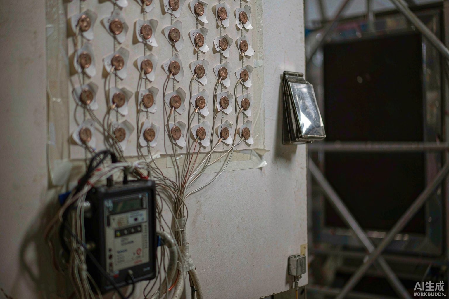
Temperature on the unexposed face is measured with a disc thermocouple — a copper disc 12 mm in diameter and 0.2 mm thick, covered by an insulating pad 30 mm × 30 mm × 2 mm [5]. The disc format exists because a bare bead bonded to a surface reads low: it is cooled by the air behind the specimen as well as heated by the specimen. Insulation is lost when the average unexposed-face temperature rise exceeds 140 K or the rise at any single point exceeds 180 K. Note what those two numbers do: the average limit is the one governing overall heat transfer, while the point limit catches local hot spots at joints, fixings and frame edges — which is where real assemblies usually fail first.
Pressure, gaps and flames
Furnace pressure is held at a small positive differential so that hot gases flow out through any opening rather than being drawn in, and it is measured with probes accurate to ± 2 Pa [5]. Integrity failures are found by observation and by gauges rather than by a number: ignition of a cotton pad held against the unexposed face, a 6 mm gap gauge passing through a crack and travelling along it, a 25 mm gauge passing through, or sustained flaming on the unexposed face [5].
Fire Resistance Test Furnace Geometries
| Geometry | Element families it serves | What drives the choice |
|---|---|---|
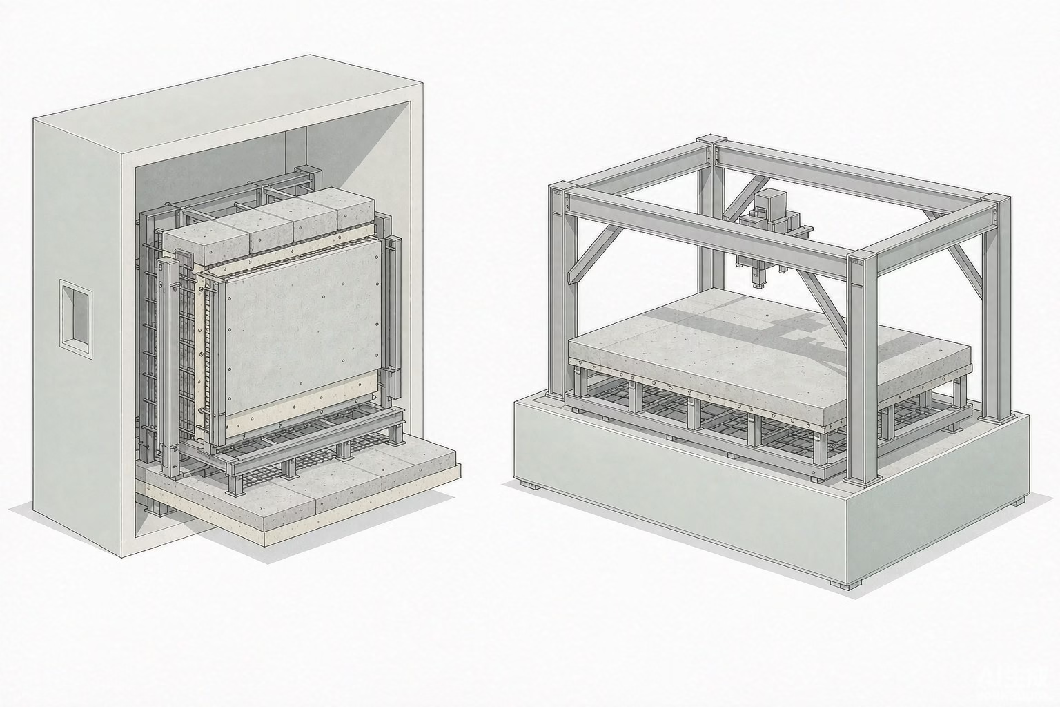
| Vertical furnace | Walls, partitions, doorsets, glazed screens, shafts | The element is mounted upright in the opening; opening height decides the tallest assembly |
| Horizontal furnace | Floors, roofs, beams, slabs | The element forms the lid or floor of the chamber and is loaded from above |
| Column furnace | Columns and other loadbearing vertical members | Load is applied axially; capacity and platen geometry dominate the design |
| Special-purpose | Cables, fire-retardant coatings, small or non-standard assemblies | The standard being cited usually prescribes the geometry directly |
BRT builds both main geometries: a vertical integrated fire resistance test furnace for walls, partitions and doorsets, and a horizontal fire resistance test furnace for floors, roofs and beams. Steelwork and cables sit in the last row, served by a steel fire-retardant coating test furnace and a cable fire resistance tester.
The practical point is that “a fire resistance furnace” is a family, and the family member is chosen by the element, not by the budget. A single fire resistance test furnace will not cover every row of that table. A laboratory that tests doorsets and steel coatings needs a different machine from one that tests floor slabs, even though both are called fire resistance furnaces. Where the element is structural steelwork, the key requirements for steel structures set the load and deformation limits that decide which machine you need.
From Furnace Data to a Classification
| Criterion | What it means | How failure is detected |
|---|---|---|
| R — load-bearing capacity | The element still carries its design load | Deformation and rate of deformation exceed the limits for the element type [3] |
| E — integrity | Flames and hot gases do not pass through | Cotton pad ignition; 6 mm or 25 mm gap gauge penetration; sustained flaming on the unexposed face [5] |
| I — insulation | Heat transfer to the unexposed face stays bounded | Average temperature rise > 140 K, or > 180 K at any point |
A report does not reduce to a single number. REI 90 and EI 60 differ in kind, not just in minutes: the first is a loadbearing element that held all three criteria for 90 minutes, the second a separating element judged only on integrity and insulation. Classification of the result is a separate step from the test itself, and in Europe it is carried out under EN 13501-2, whose current edition has been in force since May 2023 8. For the wider procedural picture — how a specimen goes from conditioning to a signed report — see our walkthrough of how fire resistance is tested for building materials.
What Changed When ISO 834-1 Was Republished in 2025
The edition question is not academic when you are specifying a fire resistance test furnace, because the control system is programmed against one particular edition. ISO 834-1:2025 entered into force on 30 May 2025 [1]. On the same day, the first edition ISO 834-1:1999 was withdrawn, along with its two amendments and the commentary document ISO/TR 834-3:2012 [2]. The European counterpart EN 1363-1 went through the same kind of change earlier: the 2012 edition was withdrawn on 19 February 2020 and replaced by EN 1363-1:2020 [3]4. Two consequences follow for anyone buying a furnace or writing a test specification. A quotation or a test report that cites “ISO 834” without an edition year is not a complete reference, and the difference is not cosmetic — a furnace control system and a laboratory procedure written against the 1999 edition were written against a document that no longer exists. The second consequence is that EN 1363-2, which covers alternative and additional procedures, is still current at its 1999 edition 7, so a current library is a mix of dates rather than a single vintage.
Calibrating and Specifying a Fire Resistance Test Furnace
Between-laboratory scatter is the reason the standards specify hardware at all, and it is the reason two suppliers quoting the same nominal furnace are not quoting the same machine. A fuller treatment of the commercial side sits in our guide to choosing a fire testing laboratory equipment supplier. These are the questions that separate them:
| Question | Why it matters |
|---|---|
| Which edition is the control system programmed against? | ISO 834-1:2025 replaced the 1999 edition on 30 May 2025 [1][2]; a 1999-vintage controller is a legacy system |
| Are plate thermometers included, and what is the ageing and replacement procedure? | The plate thermometer is the control sensor; 1 h at 1000 °C ageing, replacement after 50 h exposure [5] |
| What is the lining material, its density and its thickness? | < 1000 kg/m³ and ≥ 50 mm over ≥ 70 % of the internal surface [5] |
| What are the probe type and accuracy for pressure? | ± 2 Pa is the instrument requirement [5] |
| What are the opening dimensions, and what is the largest element you will test in five years? | Opening size is the one decision that cannot be upgraded later |
| How many unexposed-face channels does the data system record, and at what rate? | E and I are found from the unexposed face; too few channels hides a local hot spot |
| What is the documented verification procedure, and are reference specimens included? | Furnace control is judged on delivered thermal dose, so verification is a procedure, not a certificate |
Frequently Asked Questions
Is a fire resistance furnace the same thing as a flammability tester?
No. A fire resistance furnace tests a complete building element — a wall, floor, door or column — against a standard time-temperature fire, and the result is a period in minutes against the R, E and I criteria. A flammability tester such as a cone calorimeter or a small-flame apparatus measures how a material itself behaves when ignited. The two answer different questions and their results are not interchangeable.
How hot does a fire resistance furnace actually get?
The ISO 834 cellulosic curve gives roughly 842 °C at 30 minutes, 945 °C at 60 minutes, 1006 °C at 90 minutes and 1049 °C at 120 minutes. The furnace does not reach a setpoint and hold it; it keeps climbing for the whole test, which is why burner capacity and lining design are the constraints on duration rather than on peak temperature alone.
Why did plate thermometers replace bare thermocouples?
Because a bare-wire thermocouple reads a temperature that depends on the furnace geometry, the number and position of the burners and the fuel, all of which had been identified as causes of repeatability problems between laboratories. The plate thermometer is built to receive the same thermal dose as the specimen, so the result no longer carries the furnace design with it.
What do E, I and R mean on a fire resistance report?
They are three separate criteria, each timed independently. E is integrity — flames and hot gases do not pass through, checked with a cotton pad and gap gauges. I is insulation — the average unexposed-face temperature rise stays within 140 K and the rise at any point within 180 K. R is load-bearing capacity — the element keeps carrying its design load. A classification such as REI 90 means all three held for 90 minutes.
Can one furnace test walls, floors and doors?
Not usually. A vertical furnace mounts walls, partitions and doorsets upright in the opening; a horizontal furnace tests floors, roofs and beams with the element forming the lid or floor of the chamber and the load applied from above. Buying a vertical furnace and expecting to test floor slabs is the most common specification error in this category.
Which edition of ISO 834-1 should a new specification cite?
ISO 834-1:2025, which entered into force on 30 May 2025. The 1999 first edition, its two amendments and the commentary ISO/TR 834-3:2012 were withdrawn on the same day. A quotation or report that cites “ISO 834” with no year is incomplete, and a control system written to the withdrawn edition is a legacy system.
How long does a plate thermometer last?
The thermocouple and insulating pad are replaced after 50 hours of cumulative exposure, and the assembly is aged for one hour at 1000 °C before first use. A laboratory running regular 90- and 120-minute tests should treat plate thermometer consumables as a recurring budget line and hold spares on the shelf.
Conclusion
Decide in this order. First, fix the element families you will test for the next five years, because that decides vertical, horizontal, column or special-purpose geometry. Second, size the opening to the largest assembly in that list, not to the first job. Third, name the edition of the standard you are buying against — ISO 834-1:2025 or EN 1363-1:2020 — and make the supplier state it in writing. Fourth, ask what instrumentation ships with the furnace: plate thermometers, pressure probes to ± 2 Pa, disc thermocouples for the unexposed face and enough data channels to catch a local hot spot. Fifth, ask for the verification procedure and the consumables schedule, because a furnace that cannot be verified cannot support accredited results.
BRT builds a vertical integrated fire resistance test furnace, a horizontal fire resistance test furnace, and special-purpose furnaces for steel fire-retardant coatings and for cables. Tell us the element family, the largest assembly dimension and the standard edition you are working to, and we will return a configuration with the instrument list and the verification procedure spelled out.
BRT 燃烧测试应用团队 — Shenyang Baoruitong Automation Equipment. Fire testing application engineering; sources are the ISO, CEN and ASTM standard pages and official ISO preview documents cited below.
Sources
- UNI Ente Italiano di Normazione — ISO 834-1:2025
- UNI Ente Italiano di Normazione — ISO 834-1:1999
- UNI Ente Italiano di Normazione — EN 1363-1:2020
- UNI Ente Italiano di Normazione — EN 1363-1:2012
- iTeh Standards — ISO/TR 834-3:2012
- ASTM International — E119 Standard Test Methods for Fire Tests of Building Construction and Materials
- UNI Ente Italiano di Normazione — EN 1363-2:1999
- UNI Ente Italiano di Normazione — EN 13501-2:2023